1 Introduction
1-1 About this document
Thank you for purchasing the Cerevo LiveShell X.
This document is a manual that explains how to use the LiveShell X (hereafter referred to as “this product”). Please read this manual thoroughly before use and make sure you fully understand how to use the product correctly before using it.
Applicable products
This manual applies to the products listed in the table below.
Product Number |
Product Name |
|---|---|
CDP-LS04A |
LiveShell X |
CDP-LS04A-SDJ1 |
|
CDP-LS04A-SDS6 |
|
CDP-LS04A-SDK |
|
CDP-LS04A-SDR |
|
CDP-LS04A-SP |
The product(s) to which this manual applies is hereinafter referred to as “this product.”
Scope of Description
This manual describes all the information required to use this product, including how to install it, how to configure it, operation procedures, and restrictions. In addition to this manual, the following documents are provided:
Quick Setup Guide which is included with the product
Online manual for firmware versions Rev.2090 and earlier.
Release notes for each firmware version
Revision Information
このマニュアルは第1.1版(2025年5月9日公開)です。このマニュアルは LiveShell X の以下のレビジョンに適用します。
Revision History
Version 1.0 (released March 31, 2025)
First Edition
Version 1.1 (released May 9, 2025)
Minor corrections, such as typographical errors, were made.
Prerequisites Knowledge
This manual is written on the assumption that the reader has the following knowledge:
How to connect video devices to each other using HDMI cables
How to connect audio devices to each other using audio signal cables
Basic understanding of local networks using Ethernet (IEEE 802.3) and wireless LAN (IEEE 802.11)
Basic understanding of IP network operation and interface settings
How to register for use on a live video streaming platform and obtain a stream key, etc.
1-2 For your safety
Meaning of notations
In this chapter, text beginning with a warning or caution explains very important information for using this product safely. Warning and caution indicate the following items, respectively.
Warning
This indicates that failure to follow this instruction may result in death or serious personal injury.
Caution
This indicates that failure to follow this instruction may result in personal injury or damage to the equipment.
Safety warnings and precautions
In the event of an abnormal situation
Warning
If an abnormality occurs, such as smoke coming from this product or cables, immediately stop using the product and unplug the power cable. Continued use may result in breakdown, electric shock, or fire. After making sure that smoke has stopped, contact your retailer or our support center. Do not attempt to repair the product yourself as this is dangerous.
About power supply
Warning
Use a power supply and power supply cable that meets all the requirements described in this manual. Using non-compliant cables may result in this product failure, electric shock, heat generation, smoke, or fire.
Warning
Do not use the power supply cable if it is damaged, has exposed wires, or is broken. This may result in this product failure, electric shock, heat generation, smoke, or fire.
Warning
Do not use the power supply connector if there is dust or other foreign matter or liquid on it. This may result in this product failure, electric shock, heat generation, smoke, or fire.
Temperature rise
Caution
The surface of this product may become hot due to heat dissipation, and touching it may cause burns. Please handle with care during use and even after use until the temperature has dropped.
Prohibited actions
Warning
Do not disassemble or modify this product. Doing so may result in this product failure, electric shock, overheating, smoke, or fire.
Warning
Do not short-circuit the connectors of this product or connect devices that deviate from the instructions in this manual. Doing so may result in this product failure, electric shock, overheating, smoke, or fire.
Warning
When connecting external devices to this product, turn off the power to all devices. Connecting with the power on may cause malfunction or damage.
Installation environment
Caution
Do not use this product in the following conditions or under the following environmental conditions. It may malfunction, break down, or become deformed.
Places exposed to direct wind from a heater or air conditioner, or places with sudden temperature changes
Places exposed to direct sunlight, or inside a car under the hot sun
Places exposed to sea breezes, or places with continuous high humidity
In liquid or in a corrosive atmosphere
Places with strong vibrations
Places with strong electromagnetic waves
Places where static electricity or electrification occurs
Other conditions similar to these
2 Function overview
This chapter describes an overview of this product.
2-1 What you need in addition to this product
To use this product, you will need to prepare the following external devices separately (this list is an example, and the actual devices you need will vary depending on how you use it).
A device that runs a web browser to operate this product (PC, tablet, smartphone, etc.)
A video source device that can output video and audio via HDMI, such as a camera
Equipment required to build a communications network that meets the 2-2 Network Requirements
Cables, connectors, etc. to connect these
2-2 Network Requirements
To use this product, this product must be connected to a network that meets the following requirements.
The network must be able to communicate with the Internet via IPv4.
It can be used in a closed network, but some functions may be restricted.
LiveShell Remote cannot be used in a closed network.
IPv4 must be able to receive IP addresses via DHCP.
IPv4 can also be set to a fixed address manually.
The network must not require proxy settings or web login to connect.
This product does not support connections via a proxy. It also does not support networks that require web browser login authentication, such as free Wi-Fi provided by facilities.
At least the following ports must be able to communicate without any problems.
80/tcp (used by the web application in this product)
1935/tcp (when using RTMP)
443/tcp (when using RTMPS)
443/tcp and 6275/tcp (when using LiveShell Remote)
554/tcp (standard port for the RTSP server in this product)
3 Names and Functions of Each Part
The names and functions of each part of this product are as shown in the diagram below.
3-1 Names of Each Part
Front
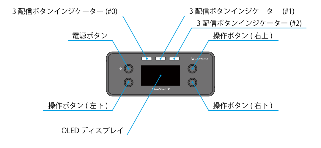
Power Button
This button is used to turn this product on and off.
Operation Button
This button is used to operate the settings of this product. There are four buttons used to move the cursor and enter values.
3Streaming Button Indicator
This button is used to start and stop streaming. The button is internally illuminated and indicates the streaming status with light.
OLED display
This display shows the operating status of this product in text, etc. A menu is displayed when configuring settings using the main unit’s control dial.
Rear
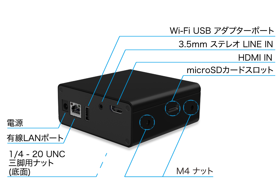
Power
This is the power input terminal for this product.
Wired LAN Port
This is a 100BASE-TX Fast Ethernet interface for connecting this product to a network.
Wi-Fi USB Adapter Port
This is a USB A terminal for connecting a wireless LAN adapter or USB communication adapter to this product.
3.5mm Stereo LINE IN
This is a 3.5mm stereo jack for inputting line-level analog audio signals to this product.
HDMI IN
This is an HDMI input terminal for inputting video and audio signals to this product.
Left Side
microSD card slot
Terminal for inserting a microSD card used for recording video.
M4 nut
Nut for fixing this product.
Right side
1/4-20 UNC nut for tripod
Nut for attaching this product to a tripod, etc.
M4 nut
Nut for fixing this product.
Bottom
1/4-20 UNC nut for tripod
Nut for attaching this product to a tripod, etc.
3-2 Settings and operation methods
You can change the settings of this product and operate its various functions by using the buttons on the front of the product, or by using the web application LiveShell Studio for LiveShell X (hereafter referred to as “LiveShell Studio”) built into the product. The features of each method are as follows, and you can use them according to the operation you want to perform.
Operation using the buttons on the front of the product
Operation using the buttons on the front of the product has the following features.
It can be used even when this product is not connected to a network (such as before initial setup).
There is no need to prepare external devices such as a computer for operation.
There are some functions that cannot be configured or operated using this method.
Therefore, it is suitable for simple configuration and operation.
Operation using LiveShell Studio
Operation using LiveShell Studio has the following features.
To use LiveShell Studio, the network settings for this product must be completed.
A separate device that can run a web browser, such as a PC for operation, is required.
LiveShell Studio allows you to operate all the functions of this product.
Therefore, it is suitable for more advanced settings and operations.
4 Installation and Initial Setup
This chapter describes how to install this product and connect external devices.
4-1 Video and audio input
HDMI source input
This product can input HDMI video signals as a video source. In addition, the audio signal superimposed on HDMI is connected to the audio mixer inside the device as a digital audio input.
Connect the HDMI signal to the HDMI IN terminal on the back of the main unit using an HDMI cable (sold separately).
Analog audio source input
The rear of the main unit has a 3.5mm stereo LINE IN terminal as an input terminal for analog audio sources. This input terminal can be used to connect a line-level stereo analog audio signal.
The analog audio input is connected to the audio mixer inside the device and can be mixed with the digital audio input.
4-2 Network Connection
Network connection type
You can choose from the following patterns for the network connection type of this product. Please select the appropriate connection type according to the network environment you will actually be using.
Connecting via Wired LAN
This is a usage mode in which this product is connected to the network via wired LAN.
Connect the wired LAN port on the back of the main unit to an Ethernet switch (sold separately) using a LAN cable (sold separately). After starting up the main unit, it will automatically connect to the network.
The default IP address of the interface is not set in the factory settings, and the IPv4 settings are automatically obtained by DHCP. If you are using a network where DHCP is not available or if you need to manually set the IP address of the interface, follow the steps below.
Boot up this product.\ → How to start up this product
Access the following website on the operating terminal.\ https://ls-local.cerevo.com/
Select “Ethernet” under “Network Settings.”
Check “Use fixed IP address.”
Enter any value for “LiveShell IP Address”, “Subnet Mask”, “Default gateway address”, and “DNS Server Address”.
Press the “Next” button.
Connect the 3.5mm stereo LINE IN jack on the back of the unit to the 3.5mm audio jack on the operation device using the setting cable included with this product.
Once the connection is complete, press the “Play” button.
When playback ends, the device will automatically connect to the network.
Tip
Data transferred from the control terminal to this product is sent as sound (similar to a fax).\ Therefore, if the control terminal is set in the following conditions, the settings may not be performed correctly.
The volume is set too low
Other sounds such as music are mixed in
Connect the setting cable to the 3.5mm audio jack on the operation device itself. If it is connected to the 3.5mm audio jack of an externally connected device such as a USB hub, the sound may not be output correctly depending on the settings on the operation device itself. In that case, please check the audio output settings on the operation device itself.
Connecting via wireless LAN
This is a usage mode in which this product connects to a network via wireless LAN.
When connecting via wireless LAN, please follow the procedure below.
Connect the wireless LAN adapter to the Wi-Fi USB adapter port on the back of the main unit.
Boot up this product.\ → How to start up this product
Access the following website on the operating terminal.\ https://ls-local.cerevo.com/
Select “Wi-Fi (Wireless LAN)” in “Network Settings.”
Enter the SSID and password of the wireless LAN network you want to connect to in “SSID (Wireless network name)” and “Password (Wi-Fi passphrase)”. If you want to use stealth mode or a fixed IP, check “Use stealth-mode access point” and “Use fixed IP address” and enter the required information.
Press the “Next” button.
Connect the 3.5mm stereo LINE IN jack on the back of the unit to the 3.5mm audio jack on the operation device using the setting cable included with this product.
Once the connection is complete, press the “Play” button.
When playback ends, the device will automatically connect to the network.
Tip
Data transferred from the control terminal to this product is sent as sound (similar to a fax).\ Therefore, if the control terminal is set in the following conditions, the settings may not be performed correctly.
The volume is set too low
Other sounds such as music are mixed in
Connect the setting cable to the 3.5mm audio jack on the operation device itself. If it is connected to the 3.5mm audio jack of an externally connected device such as a USB hub, the sound may not be output correctly depending on the settings on the operation device itself. In that case, please check the audio output settings on the operation device itself.
Tip
Please use the wireless LAN adapter (CDP-WF02A) specified by Cerevo. Wireless LAN adapters other than the one specified by Cerevo will not work properly.
Connecting via a USB data communication terminal
This is a usage form in which this product is connected to the network via a USB data communication terminal.
When connecting via a USB data communication terminal, please follow the procedure below.
Connect the USB data communication terminal to the Wi-Fi USB adapter port on the back of the main unit.
Boot up this product.\ → How to start up this product
Access the following website on the operating terminal.\ https://ls-local.cerevo.com/
Select “3G/4G Network” in “Network Settings.”
Enter the required information for “User Name”, “Password”, and “APN”.
Press the “Next” button.
Connect the 3.5mm stereo LINE IN jack on the back of the unit to the 3.5mm audio jack on the operation device using the setting cable included with this product.
Once the connection is complete, press the “Play” button.
When playback ends, the device will automatically connect to the network.
Tip
Data transferred from the control terminal to this product is sent as sound (similar to a fax).\ Therefore, if the control terminal is set in the following conditions, the settings may not be performed correctly.
The volume is set too low
Other sounds such as music are mixed in
Connect the setting cable to the 3.5mm audio jack on the operation device itself. If it is connected to the 3.5mm audio jack of an externally connected device such as a USB hub, the sound may not be output correctly depending on the settings on the operation device itself. In that case, please check the audio output settings on the operation device itself.
Tip
Please use a compatible USB data communication terminal. USB data communication terminals other than the compatible models will not work properly.
Compatible models are as follows:
D-Link DWM-221 – Revision B
NTT docomo L-03D
ZTE MF-820
Verizon U620L(※)
Huawei E3131i-2(※)
Huawei E3372(※)
ピクセラ PIX-MT100(※)
ピクセラPIX-MT110(※)
For models marked with (※), you will need to set the APN from the settings page built into the USB data communication terminal in advance. Please set the APN for the USB data communication terminal from a PC or other device before use.
4-3 Power Supply
Specifying the power supply device
This product can be powered using our designated AC adapter (CDP-ADP01A) and the dedicated built-in battery (CDP-LS04A-BAT2). No other power supplies can be used.
Connecting the power supply device to this product
This product has two power input terminals: the AC adapter on the back and the dedicated built-in battery on the bottom. Connect the power supply device specified in this manual to these power input terminals to supply power.
Tip
You can also remove the dedicated built-in battery and use only the AC adapter for power supply.\ →How to remove the built-in battery
How to start up this product
To start up this product, follow the steps below.
This can be done from the UI of the device. It cannot be done from LiveShell Studio.
Push and hold the power button on the top left of the front panel.
When boot-up begins, the Cerevo logo will appear on the OLED display, and then the OLED display will turn off for a few seconds.
The LiveShell X logo will appear on the OLED display, and the device will enter its final operating state. It is not a malfunction if the OLED display turns off during boot-up.
How to shut down this product
To shut down this product, please follow the steps below.
This operation can be performed from LiveShell Studio or the main UI.
Setting using LiveShell Studio
Press the “Power OFF” button displayed in “Status”.
Press the “OK” button displayed in the confirmation dialog.
The shutdown process will be performed and the power will be turned off.
Setting using the unit buttons
When the unit is offline
Press the operation button at the top left of the offline top screen once.
Press the operation button at the bottom left.
The shutdown process will be performed and the power will be turned off.
When the unit is online
Press the operation button at the top left of the online top screen once.
Press the operation button at the bottom left.
The shutdown process will be performed and the power will be turned off.
If you unplug the power without shutting down this product, data stored inside this product, such as setting data and caption images, may be damaged or lost.
How to restart this product
To restart this product, follow the steps below.
This can be done from LiveShell Studio. It cannot be done from the main UI.
Press the “Reboot” button displayed in “Status”.
Press the “OK” button displayed in the confirmation dialog.
The restart process will be performed.
4-4 How to read the main status screen
When this product starts up, the main status screen showing the device’s status is displayed on the main OLED display. This display can be read as follows.
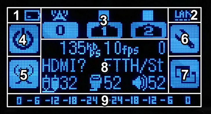
Power status pictogram\ Indicates the power supply status from the power supply.\ If power is being supplied from an AC adapter, an AC plug pictogram is displayed.\ If power is being supplied from the dedicated built-in battery, a battery pictogram is displayed.\ *If the battery pictogram shows that the bottom bar is longer than the top bar, this means that the voltage balance between the two battery cells is disrupted. In this state, the battery will drain faster than normal, so please contact support
Network interface connection status pictogram\ When the USB data communication terminal, wireless LAN adapter, or wired LAN port is connected, the respective pictogram is displayed.
Streaming status pictogram\ Indicates the streaming status of each channel. A radio tower pictogram is displayed above the icon of a channel that is currently streaming. If no streaming is being performed, a “■” is displayed.
Power Button
Offline status
Turn the power on and off.
Online status
Turn the key lock and changes to offline.
Streaming button\ Changes the streaming status.
Settings button\ Changes the settings for each channel.
Display switch button\ Switches the information displayed in the center of the OLED display.
Information display
Offline status
Displays network connection guidance
Displays firmware version
Displays connection status to LiveShell Remote and device ID
Displays wired LAN MAC address
Online status
When it’s streaming
Displays current streaming status of video and audio
When it’s not streaming
Displays each configured video and audio setting
Displays destination URL
Displays firmware version and URL for connecting to LiveShell Studio
Displays connection status to LiveShell Remote and device ID
Displays RTSP server URL for monitoring
Audio level meter\ A meter that indicates the peak level of the audio signal measured at the mixer output
5 Connecting to and operating LiveShell Studio
This chapter describes how to connect to and operate LiveShell Studio.
5-1 What is LiveShell Studio?
LiveShell Studio is a web application for operating this product that is built into the product and can be accessed via a browser on a PC, tablet, smartphone, etc. Many of the functions of this product are designed to be operated using LiveShell Studio. Below are some examples of operations that can be performed using LiveShell Studio.
Settings
Video resolution settings
Encoder bit rate settings, etc.
Network connection status and settings
Video streaming destination settings
Monitoring and operation
Subtitle composition application operation
Audio level control using the audio mixer
Starting and stopping video streaming
5-2 How to connect to LiveShell Studio
The steps to connect to LiveShell Studio are as follows.
Check the URL of LiveShell Studio
First, check the URL of LiveShell Studio from the menu of the main unit. The steps are as follows.
Push twice the operation button at the bottom right of the top screen when online.
The URL required to connect to LiveShell Studio will be displayed at the bottom.
If the network connection of this product is not properly established, the URL will be blank. In this case, please check that the network interface is properly configured.\ → 4-2 Network Connection
Connecting to LiveShell Studio from a web browser
To connect to LiveShell Studio from a web browser, follow the steps below.
Connect the PC, tablet, smartphone, etc. used for operation (hereafter referred to as the operating device) to the same subnetwork as this product.
Start a web browser on the operating device and enter the URL confirmed on the previous screen in the URL field.
If the connection is successful, the LiveShell Studio application screen will be displayed in the web browser.
5-3 How to view the LiveShell Studio screen
The LiveShell Studio application screen is displayed in a web browser. Here’s how to view it.
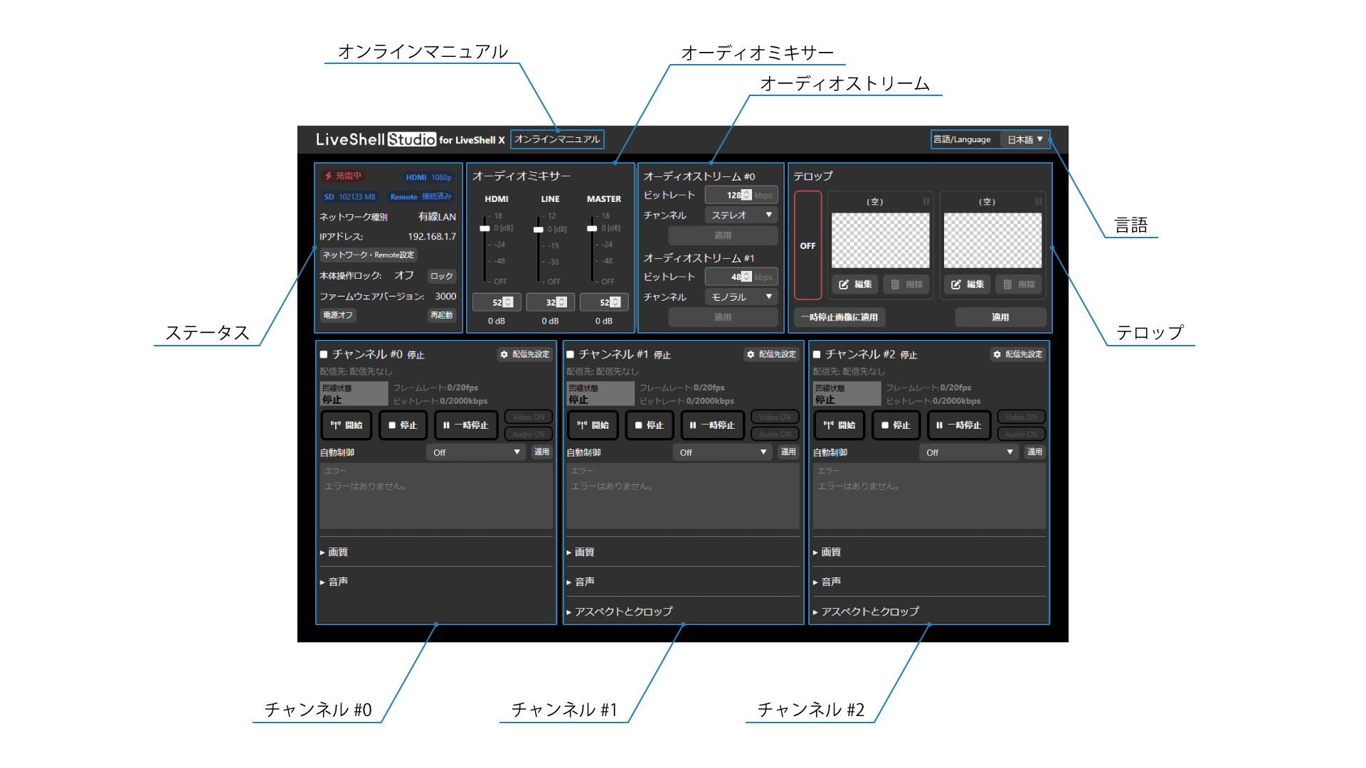
Online manual
The online manual of this product
Language
You can change the language to display. The following languages are available:
Japanese
English
Status
現在の各ステータスを表示します。表示される内容は以下のとおりです。
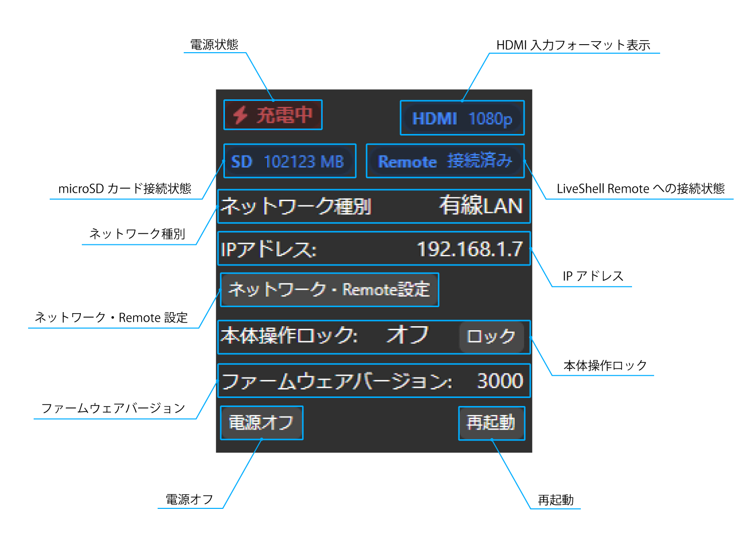
Power Status
Indicates the power supply status from the power supply.
HDMI Input Format Display
Displays the HDMI receiving format input to the HDMI IN connector. If the connection cannot be detected, this icon will be grayed out.
microSD Card Connection Status
Indicates the mount status and remaining capacity of the microSD card. If the connection cannot be detected, this icon will be grayed out.
LiveShell Remote Connection Status
If this product is properly connected to the LiveShell Remote cloud server, “Remote Connected” will be displayed in blue. If this product has been registered but the cloud server has not been connected, “Remote Not Connected” will be displayed in red. If the product is not registered to LiveShell Remote, “Remote No Config” will be displayed in gray.
Network Type
Displays the type of connection interface currently connected to the network.
IP Address
Displays the IP address of this product.
Network & Remote Settings
Opens the network and LiveShell Remote settings dialog.
Key Lock
You can turn on or off the lock function that disables the buttons on the device.
Firmware Version
Displays the firmware version of this product.
Power OFF
You can shut down this product.
Reboot
You can restart this product.
オーディミキサー
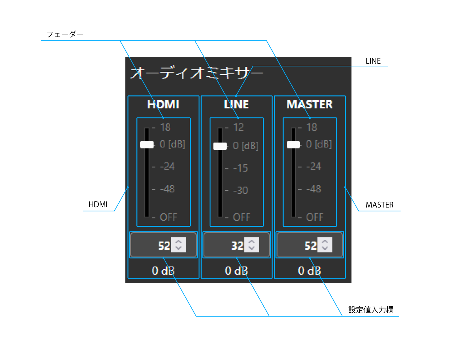
Fader
You can adjust the level of each sound by dragging and dropping.
Setting value input field
You can adjust the level of each sound by inputting directly or using the spin button.
HDMI
You can adjust the level of the digital audio source. The available ranges are as follows:
-78dB (0/OFF) to 18dB (64)
LINE
You can adjust the level of the analog audio source. The available ranges are as follows:
-48dB (0/OFF) to 12dB (40)
MASTER
You can adjust the level of the output audio after mixing. The available ranges are as follows:
-78dB (0/OFF) to 18dB (64)
オーディオストリーム
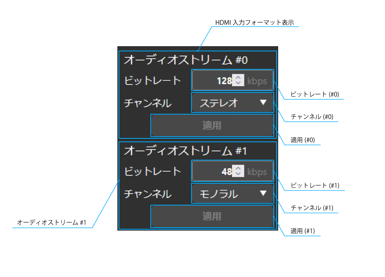
Bitrate
You can set the audio bitrate. The available ranges are as follows:
16kbps to 255kbps
Channel
You can set the channel for the input audio. The available channels are as follows:
Monaural
Mono (Left)
Mono (Right)
Stereo
Caption
You can set caption.
Channel #0
チャンネル#0の各配信設定および操作を行うことができます。
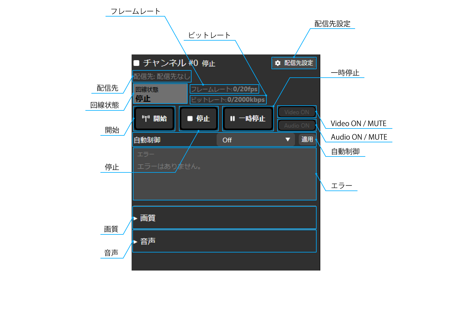
Live streaming destination setting
Open the destination setting dialog.
Destination
The current destination protocol is displayed.
Line status
The current line status is displayed. The displayed statuses are as follows.
Excellent
Good
Warning
Emergency
Dead
Stopped
Framerate
The video frame rate and the current actual frame rate are displayed.
Bitrate
The video bit rate and the current actual bit rate are displayed.
Start
You can start the video streaming.
Stopped
You can stop the video streaming.
Pause
You can pause the video streaming.
Video ON / MUTE
You can mute the streaming video.
Audio ON / MUTE
You can mute the streaming audio.
Automatic control
You can set it to follow other channels. The available settings are as follows.
Off
Auto start
Follow channel #1
Follow channel #2
Error
An error message is displayed.
Image quality
Preset
You can set the preset setting value according to the network bandwidth you use. The available settings are as follows:
Custom
Image quality priority, 300kbps
Image quality priority, 500kbps
Image quality priority, 800kbps
Image quality priority, 2000kbps
Image quality priority, 4000kbps
Motion priority, 300kbps
Motion priority, 500kbps
Motion priority, 800kbps
Motion priority, 2000kbps
Motion priority, 4000kbps
Bitrate
You can set the bit rate of the video. The available range is as follows:
32kbps ~ 20000kbps
Framerate
You can set the frame rate of the video. The available range is as follows:
1fps ~ 60fps
Key frame interval
You can set the interval for inserting key frames (i frames) of the video. By default, it is set to 3 times the frame rate setting (3 seconds). The available range is as follows:
0frame ~ 300frame
Rate control
When the communication bandwidth required for streaming is insufficient, you can set whether to change the image quality or frame rate to adjust. The available settings are as follows.
Variable image quality
Variable frame rate
Streaming queue length
You can set the size (length) of the waiting area that temporarily buffers the streaming video. The available ranges are as follows.
0 ~ 4000
Codec (RTSP/recording/TS-UDP only)
Set the codec for the streaming video. H.265 can only be set when the streaming destination is recording or RTSP. Also, if you want to change the video codec, please stop streaming. Changes will not be reflected during streaming. The available settings are as follows.
H.264
H.265
H.264 profile
Set the profile of the H.264 codec for the streaming video. If the codec is H.265, the only profile available is Main. If you want to change the H.264 profile, please stop streaming. Changes will not be reflected during streaming. The available settings are as follows.
Baseline
Main
High
Audio
Audio stream
You can set the channel for the audio stream. The available settings are as follows:
#0
#1
Adjust audio delay
You can set the delay compensation for the analog audio source. The available range is as follows:
0ms ~ 1023ms
Channel #1
チャンネル#1の各配信設定および操作を行うことができます。
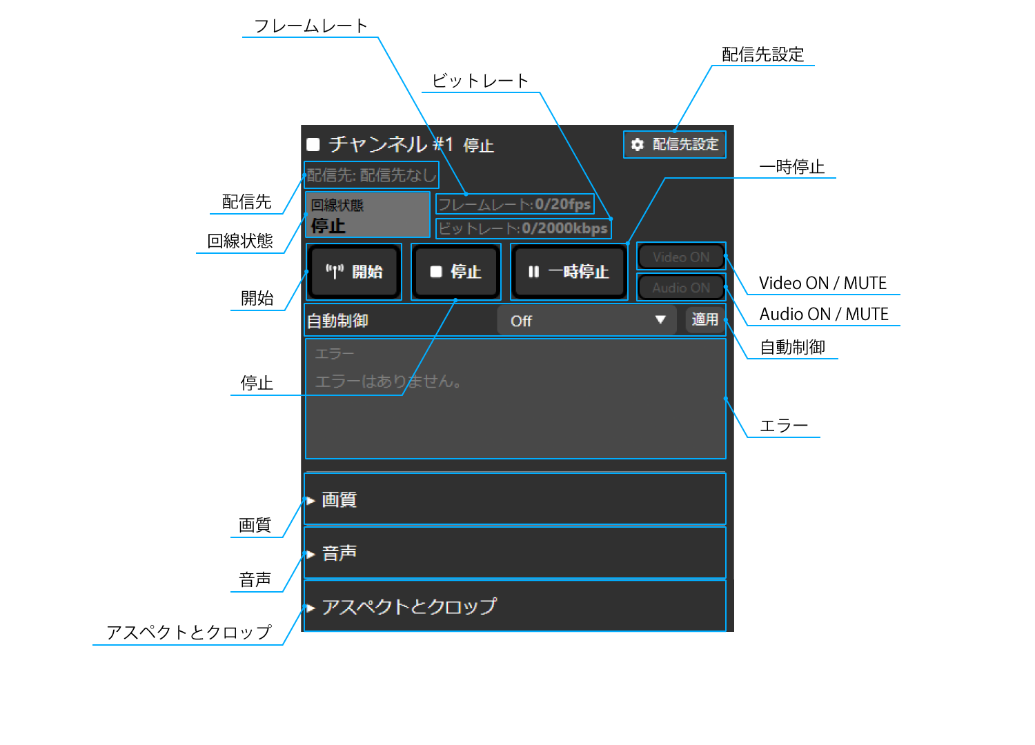
Live streaming destination setting
Open the destination setting dialog.
Destination
The current destination protocol is displayed.
Line status
The current line status is displayed. The displayed statuses are as follows.
Excellent
Good
Warning
Emergency
Dead
Stopped
Framerate
The video frame rate and the current actual frame rate are displayed.
Bitrate
The video bit rate and the current actual bit rate are displayed.
Start
You can start the video streaming.
Stopped
You can stop the video streaming.
Pause
You can pause the video streaming.
Video ON / MUTE
You can mute the streaming video.
Audio ON / MUTE
You can mute the streaming audio.
Automatic control
You can set it to follow other channels. The available settings are as follows.
Off
Auto start
Follow channel #0
Follow channel #2
Error
An error message is displayed.
Image quality
Preset
You can set the preset setting value according to the network bandwidth you use. The available settings are as follows:
Custom
Image quality priority, 300kbps
Image quality priority, 500kbps
Image quality priority, 800kbps
Image quality priority, 2000kbps
Image quality priority, 4000kbps
Motion priority, 300kbps
Motion priority, 500kbps
Motion priority, 800kbps
Motion priority, 2000kbps
Motion priority, 4000kbps
Bitrate
You can set the bit rate of the video. The available range is as follows:
32kbps ~ 20000kbps
Framerate
You can set the frame rate of the video. The available range is as follows:
1fps ~ 30fps
Key frame interval
You can set the interval for inserting key frames (i frames) of the video. By default, it is set to 3 times the frame rate setting (3 seconds). The available range is as follows:
0frame ~ 300frame
Vertical resolution
You can set the vertical resolution of the video you are streaming. The available settings are:
240px
360px
480px
720px
1080px
Rate control
When the communication bandwidth required for streaming is insufficient, you can set whether to change the image quality or frame rate to adjust. The available settings are as follows.
Variable image quality
Variable frame rate
Streaming queue length
You can set the size (length) of the waiting area that temporarily buffers the streaming video. The available ranges are as follows.
0 ~ 4000
Codec (RTSP/recording/TS-UDP only)
Set the codec for the streaming video. H.265 can only be set when the streaming destination is recording or RTSP. Also, if you want to change the video codec, please stop streaming. Changes will not be reflected during streaming. The available settings are as follows.
H.264
H.265
H.264 profile
Set the profile of the H.264 codec for the streaming video. If the codec is H.265, the only profile available is Main. If you want to change the H.264 profile, please stop streaming. Changes will not be reflected during streaming. The available settings are as follows.
Baseline
Main
High
Audio
Audio stream
You can set the channel for the audio stream. The available settings are as follows:
#0
#1
Adjust audio delay
You can set the delay compensation for the analog audio source. The available range is as follows:
0ms ~ 1023ms
Aspect and Crop
Crop mode
You can set the aspect ratio of the screen to be streamed. The available settings are as follows:
Auto
4:3
16:9
4:3 Side Cut
16:9 Letterbox
Manual
Overscan ratio
You can set the overscan ratio. The available ranges are as follows:
0 ~ 255
Manual aspect ratio
If you select Manual as the crop type, you can manually set the aspect ratio by entering it directly or using the spin button. The available ranges are as follows:
X
0px ~ 1560px
Y
0px ~ 928px
Width
360px ~ 1920px
Height
152px ~ 1080px
Channel #2
チャンネル#2の各配信設定および操作を行うことができます。
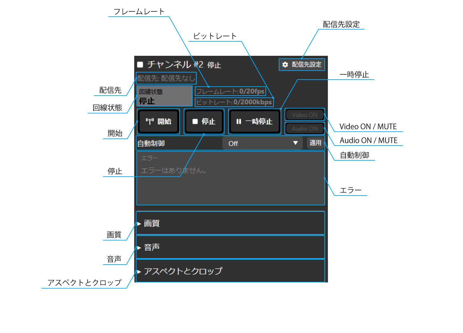
Live streaming destination setting
Open the destination setting dialog.
Destination
The current destination protocol is displayed.
Line status
The current line status is displayed. The displayed statuses are as follows.
Excellent
Good
Warning
Emergency
Dead
Stopped
Framerate
The video frame rate and the current actual frame rate are displayed.
Bitrate
The video bit rate and the current actual bit rate are displayed.
Start
You can start the video streaming.
Stopped
You can stop the video streaming.
Pause
You can pause the video streaming.
Video ON / MUTE
You can mute the streaming video.
Audio ON / MUTE
You can mute the streaming audio.
Automatic control
You can set it to follow other channels. The available settings are as follows.
Off
Auto start
Follow channel #0
Follow channel #1
Error
An error message is displayed.
Image quality
Preset
You can set the preset setting value according to the network bandwidth you use. The available settings are as follows:
Custom
Image quality priority, 300kbps
Image quality priority, 500kbps
Image quality priority, 800kbps
Image quality priority, 2000kbps
Image quality priority, 4000kbps
Motion priority, 300kbps
Motion priority, 500kbps
Motion priority, 800kbps
Motion priority, 2000kbps
Motion priority, 4000kbps
Bitrate
You can set the bit rate of the video. The available range is as follows:
32kbps ~ 20000kbps
Framerate
You can set the frame rate of the video. The available range is as follows:
1fps ~ 30fps
Key frame interval
You can set the interval for inserting key frames (i frames) of the video. By default, it is set to 3 times the frame rate setting (3 seconds). The available range is as follows:
0frame ~ 300frame
Vertical resolution
You can set the vertical resolution of the video you are streaming. The available settings are:
240px
360px
480px
720px
1080px
Rate control
When the communication bandwidth required for streaming is insufficient, you can set whether to change the image quality or frame rate to adjust. The available settings are as follows.
Variable image quality
Variable frame rate
Streaming queue length
You can set the size (length) of the waiting area that temporarily buffers the streaming video. The available ranges are as follows.
0 ~ 4000
Codec (RTSP/recording/TS-UDP only)
Set the codec for the streaming video. H.265 can only be set when the streaming destination is recording or RTSP. Also, if you want to change the video codec, please stop streaming. Changes will not be reflected during streaming. The available settings are as follows.
H.264
H.265
H.264 profile
Set the profile of the H.264 codec for the streaming video. If the codec is H.265, the only profile available is Main. If you want to change the H.264 profile, please stop streaming. Changes will not be reflected during streaming. The available settings are as follows.
Baseline
Main
High
Audio
Audio stream
You can set the channel for the audio stream. The available settings are as follows:
#0
#1
Adjust audio delay
You can set the delay compensation for the analog audio source. The available range is as follows:
0ms ~ 1023ms
Aspect and Crop
Crop mode
You can set the aspect ratio of the screen to be streamed. The available settings are as follows:
Auto
4:3
16:9
4:3 Side Cut
16:9 Letterbox
Manual
Overscan ratio
You can set the overscan ratio. The available ranges are as follows:
0 ~ 255
Manual aspect ratio
If you select Manual as the crop type, you can manually set the aspect ratio by entering it directly or using the spin button. The available ranges are as follows:
X
0px ~ 1560px
Y
0px ~ 928px
Width
360px ~ 1920px
Height
152px ~ 1080px
6 Video and Audio Settings
This chapter explains how to set up video and audio.
6-1 Video Settings
To set up video for each streaming channel, follow the steps below.
This operation can be performed from LiveShell Studio or the main UI.
Setting using LiveShell Studio
Click the “Quality” button displayed on the desired channel for which you want to set the settings.
Operate each displayed setting in the same way as above, and enter the desired value in each input field.\ See below for details on each setting.\ → 5-3 How to view the LiveShell Studio screen
Click the “Apply” button to apply the settings.
Setting using the unit buttons
Push the operation button on the top right of the main screen once while online.
Use the operation buttons on the bottom right and bottom left to move the cursor to the desired “Video Stream” channel you want to set.
Push the operation button on the top right to confirm your selection.
Operate each displayed setting in the same way as above, and enter the desired value in each input field.\ See below for details on each setting.
When setting with the main UI, the setting will be applied as soon as the desired value is entered in each input field.
6-2 Audio Settings
To configure the audio for each streaming channel, follow the steps below.
Here, use the audio mixer to adjust each audio level. This can be done from LiveShell Studio or the device UI.
For audio settings other than those mentioned above, please refer to the individual procedures below.\ → Audio stream settings\ → AV Sync Adjustment Settings
Setting using LiveShell Studio
Drag and drop the fader of the desired input that you want to operate in the “Audio Mixer” with your mouse.\ You can also directly enter any value in the input field at the bottom. In either case, the setting will be applied immediately.
Setting using the unit buttons
Push the operation button on the top right of the main screen once while online.
Use the operation buttons on the bottom right and bottom left to move the cursor to “Audio Mixer”.
Push the operation button on the top right to confirm your selection.
Operate each displayed setting in the same way as above, and enter the desired value in each input field.\ See below for details on each setting.\ → 5-3 How to view the LiveShell Studio screen
When setting with the main UI, the setting will be applied as soon as the desired value is entered in each input field.
7 Setting the destination
This chapter describes how to configure the streaming destination of this product.
By setting the destination of this product, you can transmit encoded video and audio to an IP network and record it on a recording medium.
The destination can be set in LiveShell Studio. It cannot be done in the main UI.
7-1 Overview of streaming destination settings
Destinations are the streaming destinations for the video and audio streams generated by this product’s encoder function, and can be broadly divided into network streaming and recording.
This product can simultaneously send the same stream to up to three destinations set on channel #0, channel #1, and channel #2. In addition to these, there is also a preview channel #3.
The maximum streaming resolution of this product is 1080p60, but this is the maximum, and does not mean that three 1080p60 video streamings can be handled simultaneously.\ Video streaming using this product has the following restrictions.
1080p60 streaming is only possible on channel #0. Also, when 1080p60 streaming is being operated, the streaming on other channels is not possible (however, preview streaming is possible).
The total of the four channels, channel #0, channel #1, channel #2, and channel #3, must be kept below 150Mpx/s.\ Note that 1080p60 is approximately 125 Mpx/s, 1080p30 is approximately 62.2 Mpx/s, 720p30 is approximately 27.7 Mpx/s, 480p60 is approximately 24.60 Mpx/s, and 480p30 is approximately 12.30 Mpx/s. Channel #3 is 480p30 by default.
Due to the above restrictions, the available resolution and other settings are as follows.\ *The following are only some examples, and do not list all possible combinations.
#0 |
#1 |
#2 |
|---|---|---|
1080p60 |
N/A |
N/A |
1080p30 |
1080p30 |
N/A |
1080p30 |
720p30 |
720p30 |
720p30 |
720p30 |
720p30 |
7-2 Protocols that can be used for network streaming
The application protocols that can be used for network streaming are as follows:
RTMP and RTMPS
Protocols used to send video and audio to major live streaming platforms. RTMP sends streams in plain text, while RTMPS encrypts and sends them using the Transport Security Layer. Depending on the platform, the use of RTMPS may be specified.
To stream using RTMP or RTMPS, you generally need to issue an account on the live streaming platform and obtain an RTMP URL and stream key. In addition, the recommended settings for the encoder, etc. vary depending on the platform to which you are streaming. Please check these as well before configuring this product.
RTSP Server Mode
RTSP is a function that allows this product to act as a server and stream video and audio to connected clients. It is a protocol suitable for use in local networks, such as viewing to check program output and streaming within the premises.
Stream Recording
You can also set “recording” as one of the streaming destinations. In this case, the stream is recorded in MP4 container or MPEG2-TS format on the microSD card installed in this product.
If you select MP4 as the recording container, the recorded data may be corrupted if the recording end process is not performed normally, such as if the power of this product is lost during recording.\ If you select MPEG2-TS as the recording container, the recorded data up to the time of the event will be retained even if a similar event occurs, such as the power being lost during recording.
The SD cards that can be used are limited to SD, SDHC, and SDXC cards formatted in FAT32 or exFAT format.
MPEG2-TS over UDP
MPEG2-TS over UDP is a mode in which video and audio multiplexed as MPEG2 Transport Stream are sent without any procedures as a payload of UDP datagram. This protocol is suitable for transmitting video to video decoders that can receive this protocol.
7-3 Basic operations for setting a streaming destination
To set a streaming destination, follow the steps below.
Click the “Streaming setting” button displayed in the upper right corner of any channel you want to set up to display the setting dialog.
Select any protocol from the pull-down menu in “Streaming type”.
Enter any value into the input field for each setting displayed. The setting value you need to enter varies depending on the destination type setting. Please refer to the individual steps below for each.
For RTMP client\ → RTMP Client Settings
For RTSP server\ → RTSP Server Settings
For recording\ → Recording settings
For MPEG2-TS over UDP\ → MPEG2-TS over UDP settings
When you click “Save”, the destination will be saved as the destination to be used on the channel.
7-4 Settings for each streaming destination type
RTMP Client Settings
For the destination type “RTMP client”, you need to set the following items.
In “RTMP URL”, enter the RTMP URL you obtained from the streaming platform.
In “Stream key”, enter the stream key you obtained from the streaming platform.
If you want to use RTMP authentication, click “Use RTMP authentication” and enter any value for “RTMP Username” and “RTMP Password”.
RTSP Server Settings
For the “RTSP Server” streaming destination type, you need to set the following items.
In “Port”, enter the TCP port on which the RTSP server listens. Normally, enter 554.
For “Communication Type”, select whether to send media packets by unicast or multicast. Normally, select “Unicast”.
If you select Multicast, enter the Time To Live value for multicast streaming in “TTL”.
Recording settings
For the “Recording” delivery type, you must set the following items.
In “Format”, specify the container format to use when saving the stream. Select either “MP4” or “MPEG2-TS”.
MPEG2-TS over UDP settings
For the “MPEG2-TS over UDP” streaming destination type, you must set the following items.
In “Destination address”, enter the destination IP address to which the UDP datagram will be sent.
In “Port”, enter the destination port number of the UDP datagram to be sent.
In “Multicast TTL”, enter the Time To Live value when using multicast streaming.
7-5 Starting and Stopping/Pausing Streaming or Recording
To start or stop streaming or recording for a channel you have set, follow the procedure below. This can be done from LiveShell Studio or the main UI.
Starting streaming or recording
Setting using LiveShell Studio
Click the “Start” button displayed on the desired channel to start.
Setting using the unit buttons
Push the “3 Streaming Button Indicator” of the desired channel to start while online.
Push the operation button at the bottom left on the top screen once.
Press the operation button at the bottom left that says “Start” again.
Stopping streaming or recording
Setting using LiveShell Studio
Click the “Stop” button displayed on the desired channel to stop.
Setting using the unit buttons
Push the “3 Streaming Button Indicator” of the desired channel to stop while online.
Push the operation button at the bottom left on the top screen once.
Push the operation button at the bottom right that says “Stop” once.
Pausing a broadcast or recording
Setting using LiveShell Studio
Click the “Pause” button displayed on the desired channel you wish to pause.
Setting using the unit buttons
Push the “3 broadcast button indicator” on the desired channel you wish to pause while online.
Push the operation button at the bottom left on the top screen once.
Push the operation button on the top right that says “Pause” once.
8 Remote operation settings with LiveShell Remote
This chapter describes how to configure and operate LiveShell Remote.
LiveShell Remote is a cloud service that connects to the LiveShell Studio of this product via the Internet and allows you to remotely control. It can be used when the location where this product is installed is far from the location where it is operated, or when you want to perform maintenance or operation of this product remotely.
8-1 LiveShell Remote Service Agreement
To use LiveShell Remote, you must purchase a separate service agreement and license. Please check the details of the service content on the service website below and then purchase the agreement and license.
8-2 Registering an individual LiveShell X unit to LiveShell Remote
After purchasing a license, you need to register the individual to be operated using LiveShell Remote to the cloud.
Please follow the procedure below. Individual registration can be done in LiveShell Studio. It cannot be set in the main unit UI.
Connect to LiveShell Studio for this product you wish to register for LiveShell Remote.
Click the “Network & Remote Settings” button to display the settings dialog.
Select the “LiveShell Remote” tab at the top of the dialog.
Enter the PIN code provided by the LiveShell Remote license in the “PIN code” input field under “Register this device to LiveShell Remote”.
Click the “Register” button to complete the registration of the individual to LiveShell Remote. \If registration is successful, the “LiveShell Remote Registration Status” will change to “Registered” and the device ID will be displayed.
8-3 Unregistering from LiveShell Remote
If you want to discontinue use of LiveShell Remote for an individual registered in LiveShell Remote, please follow the procedure below. You can unregister an individual in LiveShell Studio. It cannot be done in the main UI.
Connect to the LiveShell Studio of this product for which you want to unregister.
Click the “Network & Remote Settings” button to display the settings dialog.
Select the “LiveShell Remote” tab at the top of the dialog.
Press the “Remove” button in “Remove LiveShell Remote registration”.
The individual unit will now be unregistered from LiveShell Remote.
If you unregistered your LiveShell Remote, you will not be able to use LiveShell Remote until you register the LiveShell X again. Please note that unregistered your LiveShell Remote license does not delete the LiveShell Remote license.
8-4 Connecting to the LiveShell Remote Server
When an individual LiveShell X unit is registered with LiveShell Remote, it will automatically connect to the LiveShell Remote cloud server via the Internet. If a connection to the server cannot be established due to a network outage or other reasons, the server will periodically retry the connection. Please refer to the next section for how to check the connection status with the cloud server.
8-5 Checking the LiveShell Remote Connection Status
The connection status between this product and the LiveShell Remote cloud server can be checked on the main status screen of LiveShell Studio or the OLED display of this peoduct.
On LiveShell Studio, if this product is properly connected to the LiveShell Remote cloud server, “Remote Connected” will be displayed in blue. If this product has been registered but the cloud server has not been connected, “Remote Not Connected” will be displayed in red. If the product is not registered to LiveShell Remote, “Remote Not Configured” will be displayed in gray. To check the registration status and your device ID of LiveShell Remote, as well as the connection status with the cloud server, click the “Network & Remote Settings” button at the bottom and select the “Remote Settings” tab in the settings dialog that appears.
In the main status screen of the main unit, a ☁ (cloud) icon is displayed when this product is properly connected to the LiveShell Remote cloud server. If the product is registered but the cloud server is not yet established, an × icon is displayed in the corresponding area. If the product is not registered to LiveShell Remote, nothing is displayed.
To check the device ID and connection status on the device, follow the steps below.
Push the operation button in the top right of the online home screen three times.
The device ID and connection status will be displayed.
If a connection to the cloud server cannot be established and the connection is being retried, a ☁ (cloud) icon may momentarily be displayed to indicate the connection status.
9 Setting and operating captions
This chapter describes how to configure and operate the caption function of this product.
The caption function allows you to composite still images and text onto the video being streamed. You can use it to display a message to viewers or a logo on the video being streamed.
9-1 Basic method for creating and editing captions
Captions in this product are composed of multiple “layers” and are expressed as a composite result of overlapping these layers. There are two types of layers: “image layers” and “text layers.” The desired caption can be created by first creating an empty caption, and then adding the raster image and text required for the caption content as an image layer and a text layer, respectively.
When using an image layer, you must create a still image to be used as a layer in advance using an image editing software, and upload the image to the memory of this product in LiveShell Studio. Text layers can be entered and edited in LiveShell Studio.
Note that only two sets of captions can be saved.
Creating a new caption
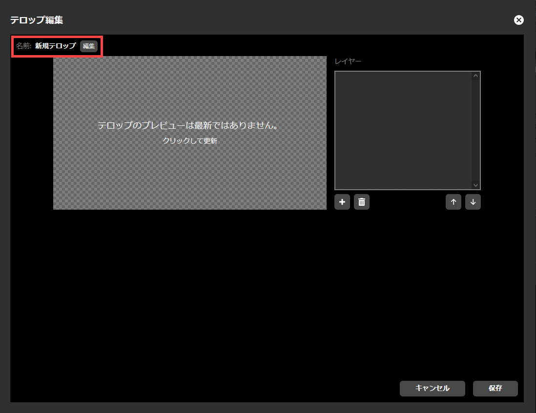
To create a new caption, please do the following.
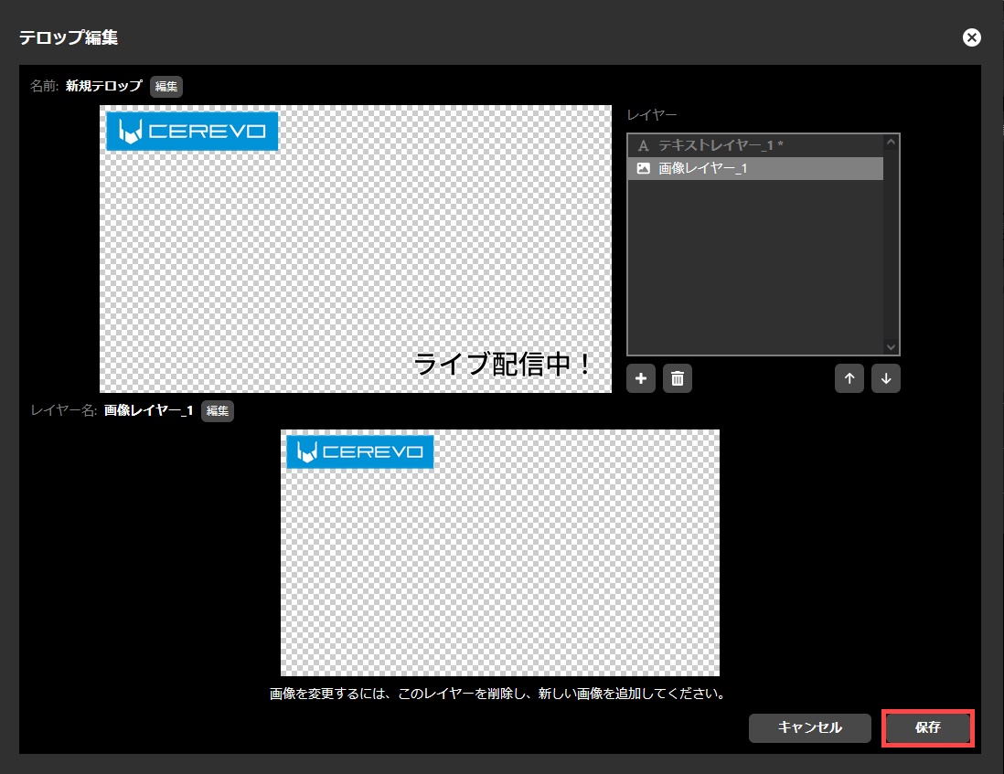
「テロップ」内に表示されている「編集」ボタンを押してください。
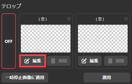
「テロップ編集」ダイアログが表示されます。この時点では、テロップの内容を構成するレイヤーはなく、一様に透明なテロップとなっています。
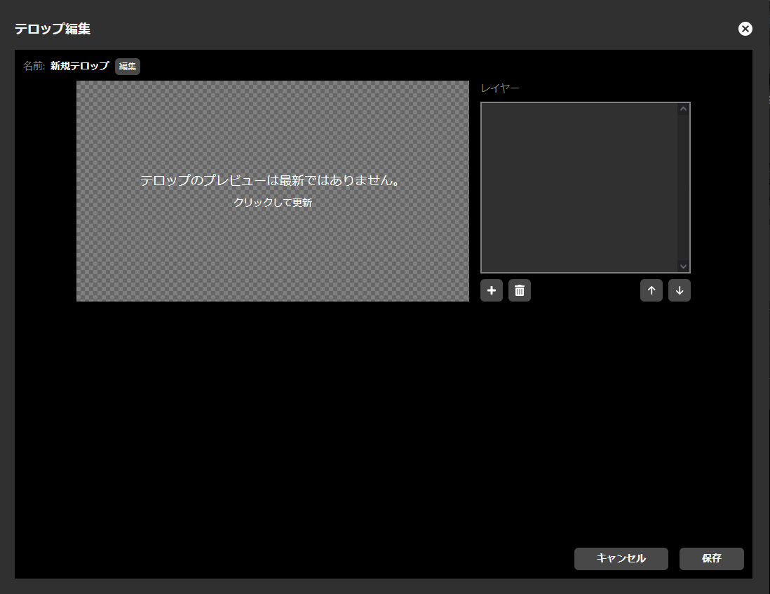
テロップには、任意の名称を付与することができます。新規で作成したテロップの名称は「新規テロップ」となっています。名称の横にある「変更」ボタンをクリックすることで、名称の変更が可能です。
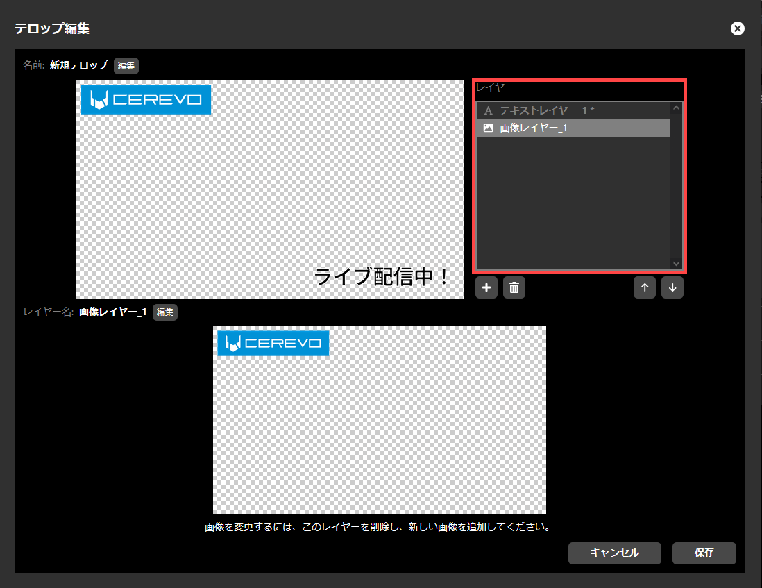
Adding a Layer
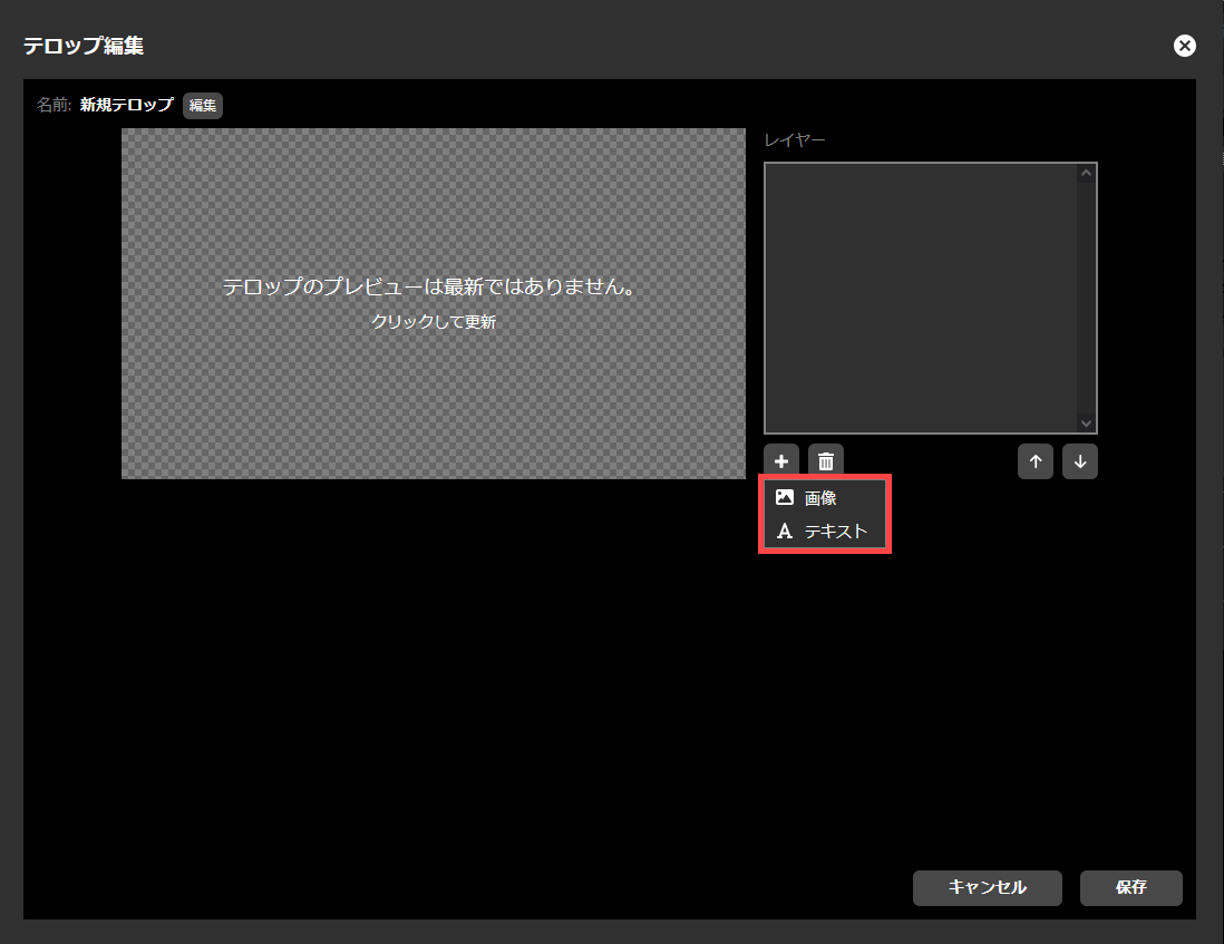
To add a new layer to a caption, do the following.
「レイヤー」内の下部に表示されている「+」ボタンを押してください。
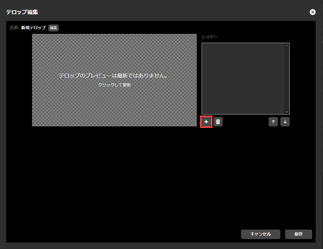
「画像」か「テキスト」のいずれかを選択するサブメニューが表示されます。画像レイヤーを追加する場合は「画像」を、テキストレイヤーを追加する場合は「テキスト」を、それぞれ選択してください。
Adding an image layer
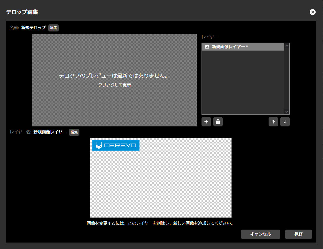
To add an image layer, please do the following.
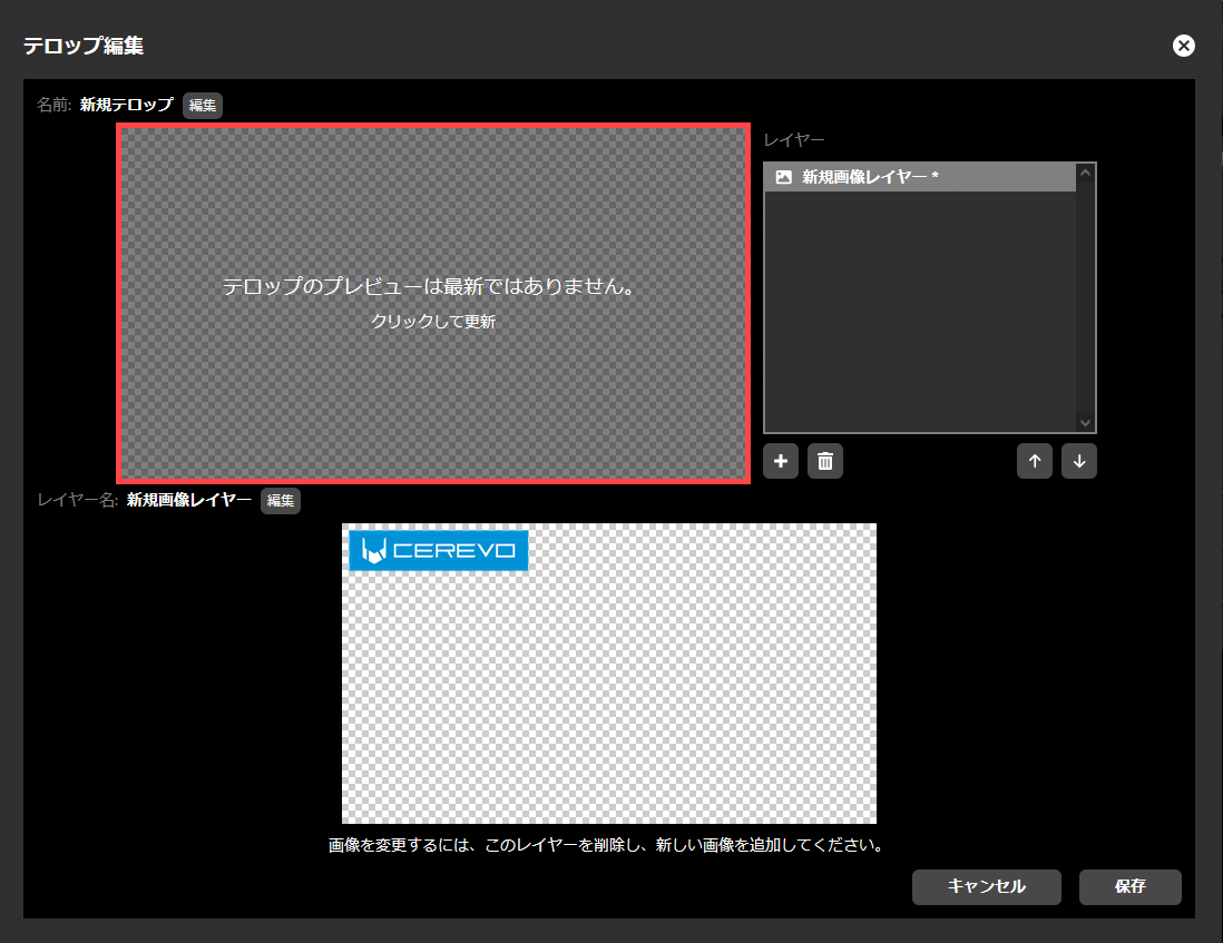
前項の「レイヤーの追加」で「画像」を選択すると、画像ファイルのアップロードを求められます。予め作成した画像ファイルを操作用端末にて選択し、アップロードを行ってください。
この画像は、以下の条件を満たすものでなければなりません。
he file format must be a PNG image.”
ファイルサイズは、4メガバイト以下であること。
なお、画像レイヤーが追加できる数は1枚のみです。
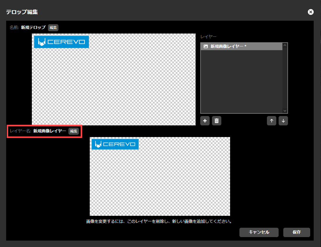
 2. プレビューは自動的には更新されません。確認する場合には「プレビュー」をクリックして更新してください。
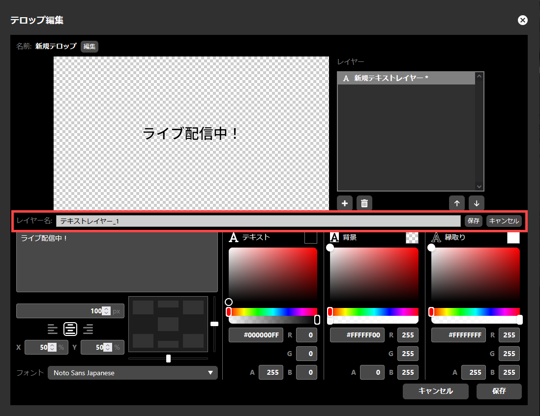
 3. レイヤー名を編集する場合には「編集」を押してください。
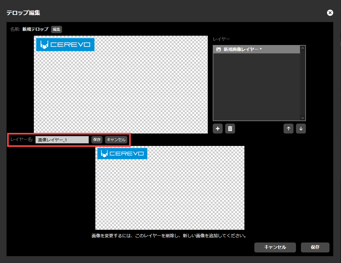
 4. 任意のレイヤー名を入力し「保存」を押してください。
 5. 全ての編集が完了したら「保存」をクリックしてください。
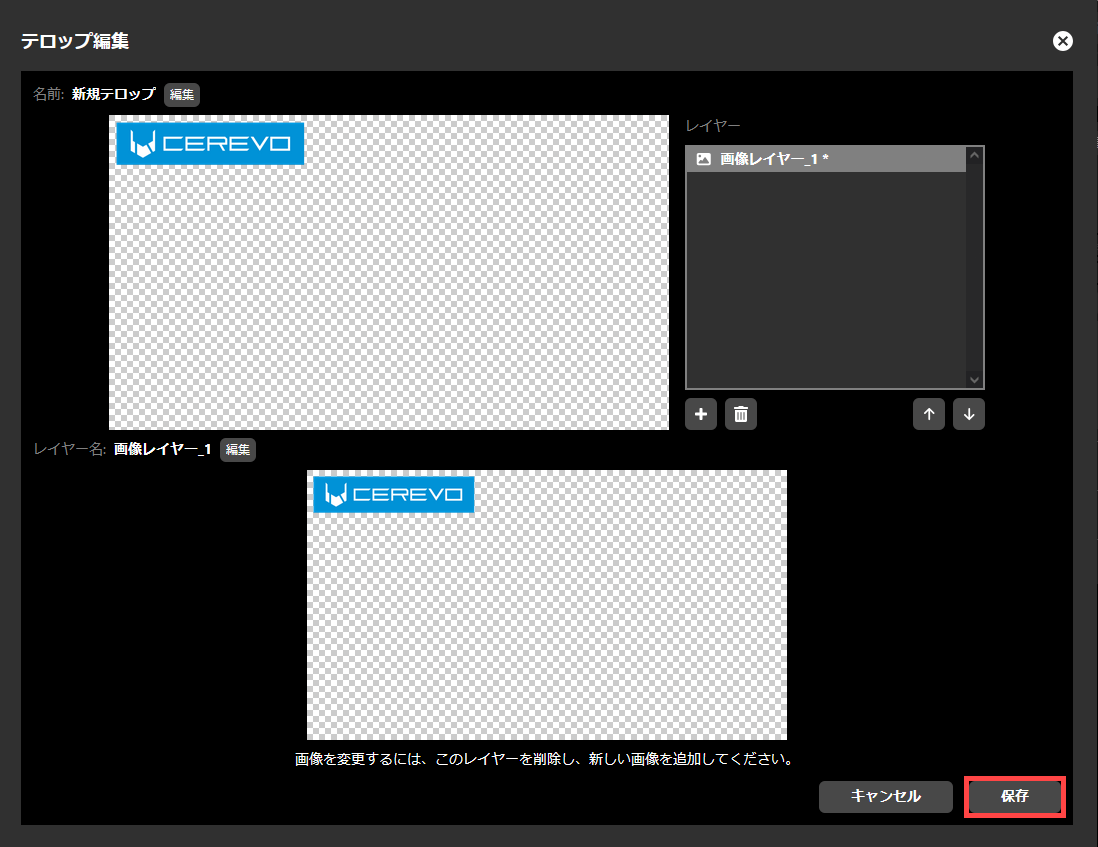 6. 保存が完了すると自動的に「テロップ編集」ダイアログが閉じられます。
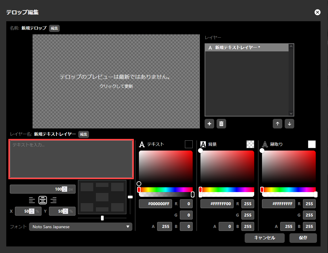
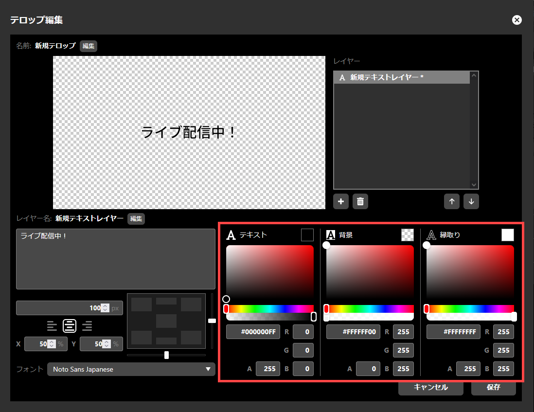
Adding a text layer
To add a text layer, do the following.
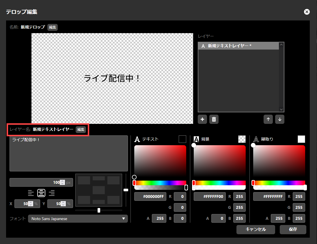
前項の「レイヤーの追加」で「テキスト」を選択すると、テキストテロップの編集画面が表示されます。
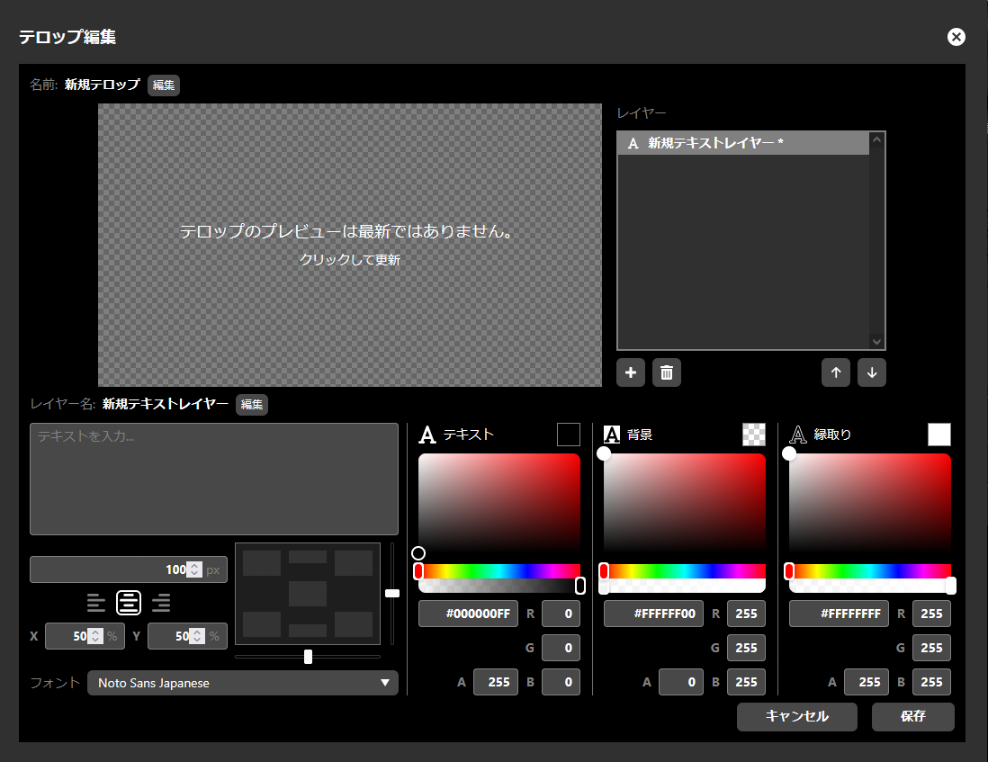 この画面では、テロップとして表示する文字の内容のほかに、テキストの大きさ、色、画面上の配置などの指示を編集することができます。
編集方法は各内容により異なります。それぞれ、以下の個別手順を参照してください。
テキストの内容
→ Text contentテキストの書体
→ Text fontテキストの大きさ
→ Text sizeテキストの水平方向の配置
→ Horizontal text alignmentテキストの位置指定
→ Specifying the text positionテキストの色および透明度
→ Text color and transparency
プレビューは自動的には更新されません。確認する場合には「プレビュー」をクリックして更新してください。

レイヤー名を編集する場合には「編集」を押してください。
任意のレイヤー名を入力し「保存」を押してください。
全ての編集が完了したら「保存」をクリックしてください。
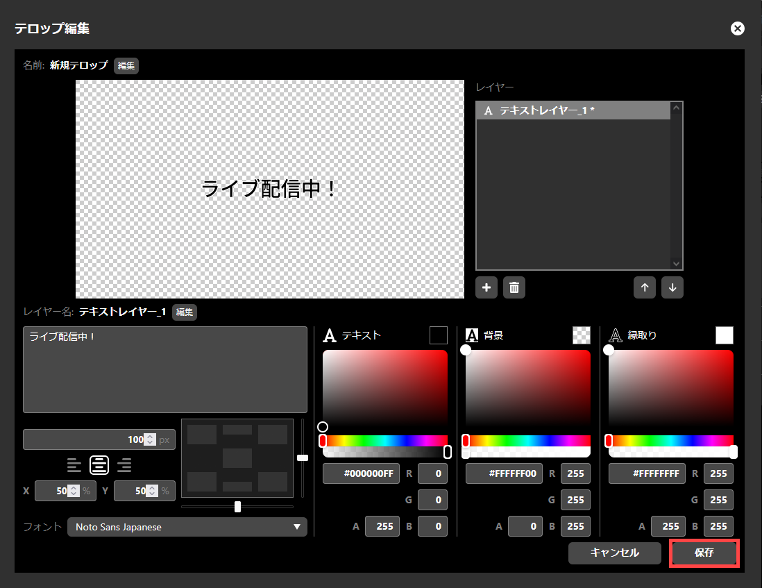
The “Caption edit” dialog will close automatically once saving is complete.
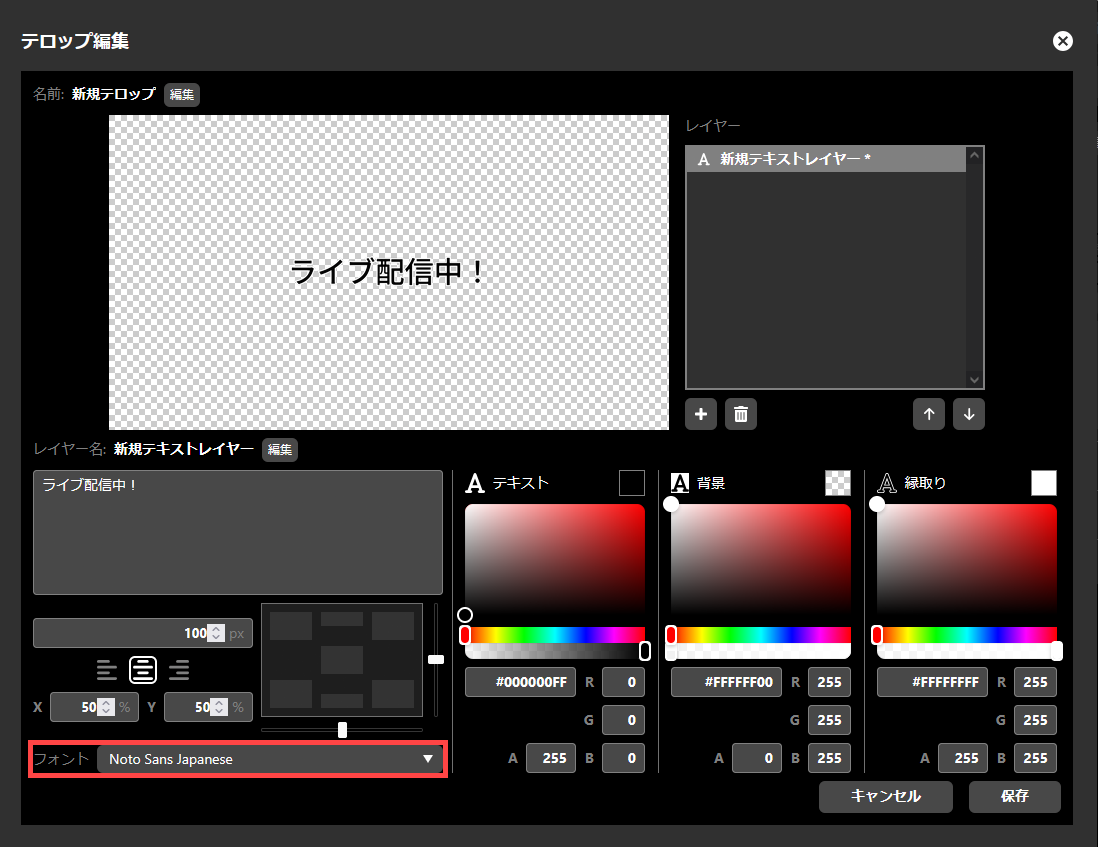
Text content
「テキストを入力…」と表示されたテキストボックス内に、テロップとして表示する任意の文字を入力してください。
Text font
テキストの書体は「フォント」内に表示されているプルダウンメニューから選択してください。
Text size
テキストの大きさは、ピクセル単位で指定できます。大きさの初期値は 100 px です。

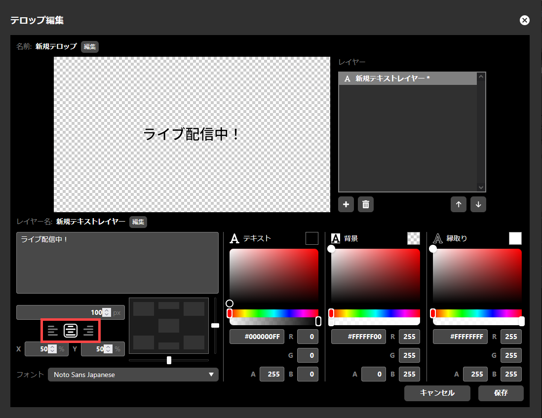
Horizontal text alignment
You can choose the horizontal alignment of text from “left justified,” “center,” or “right justified.” This selection determines which part of the text will be used as the basis for positioning when you “specify the text position” as explained in the next section. The basis for positioning is as follows:
If you select left justified, the left edge of the text
If you select center, the center of the text
If you select right justified, the right edge of the text
テキストの水平方向の配置は手動で設定できるほか、「位置指定ボックス」を使ってテキストの位置指定を行ったときには、自動的に設定が行われます。
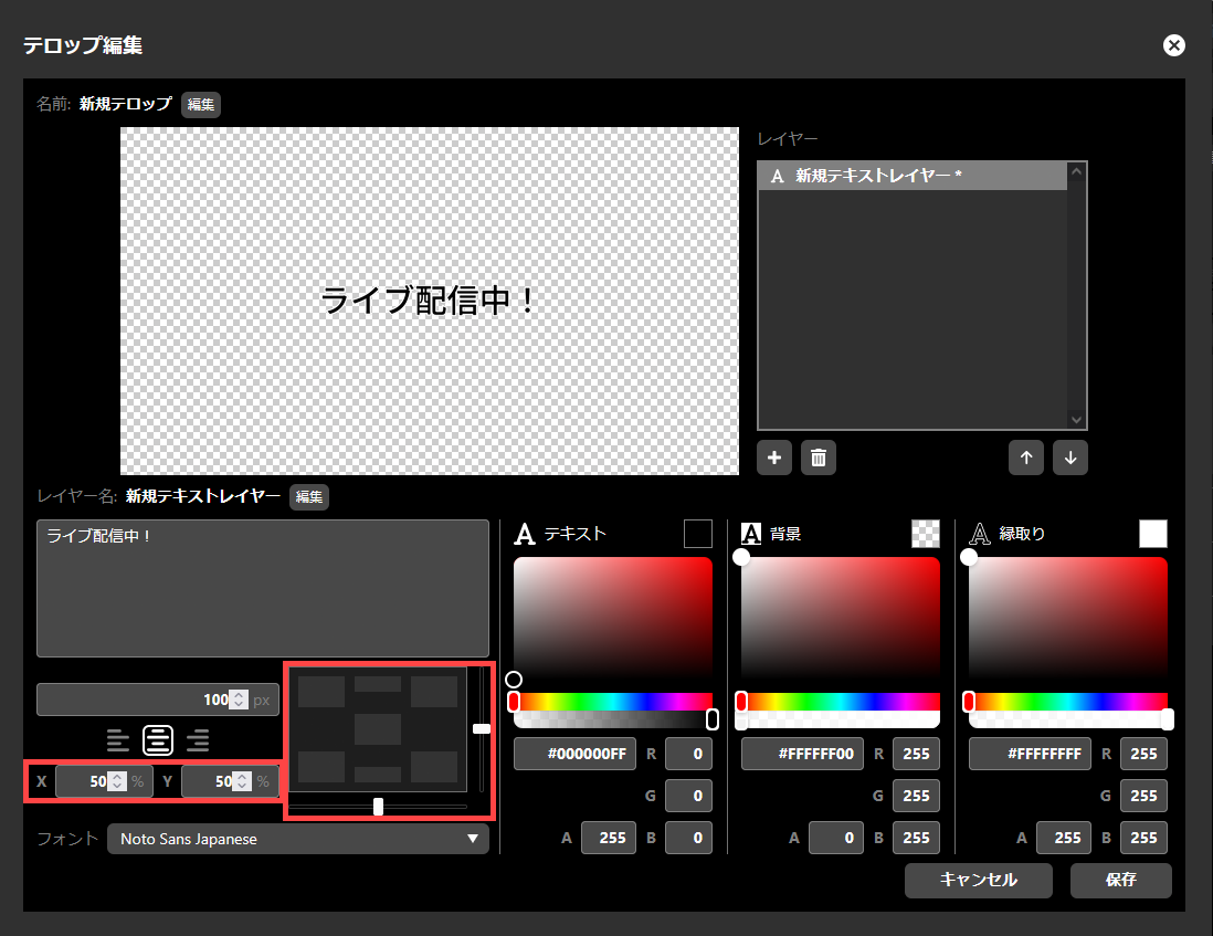
Specifying the text position
You can specify the position of text within the caption area using the position box, slider, or by entering the X/Y coordinates.
Using the position box, you can position the text in the caption area with one click to one of the following positions: “Center”, “Top center”, “Bottom center”, “Top left”, “Bottom left”, “Top right”, or “Bottom right”. The horizontal position of the text is also automatically set according to this positioning. If you position the text in the “Center”, “Top center”, or “Bottom center”, the horizontal position of the text will be set to “Center” and it will be centered within the caption area. If you position the text in the “Bottom left” or “Top left”, the horizontal position of the text will be set to “Left justified”, and the left edge of the text will be aligned to the left edge of the caption area. Similarly, if you position the text in the “Bottom right” or “Top right”, the horizontal position of the text will be set to “Right justified”, and the right edge of the text will be aligned to the right edge of the caption area.
テキスト位置の微調整は、水平方向については、位置指定ボックスの下にあるスライダーを動かすことで、垂直方向については位置指定ボックスの右にあるスライダーを動かすことで行うことができます。また、X と Y の座標に即値を入力することでも、位置の指定を行うことができます。値の単位はパーセントであり、画面上左端を原点とした水平および垂直解像度に対する比による指示となります。
Text color and transparency
You can specify the color of the text body, background, and border separately. You can also specify the transparency of each element. Areas without any of these elements will be transparent.
色の指定は、カラーピッカーによる選択、16進法の #RRGGBBAA の形式での指定、または、赤、緑、青、透明度の即値入力により行うことができます。色を即値で入力する場合は、0 が最小置、255 が最大値です。透明度は 0 で完全に透明、255 で完全に不透明となります。透明度の値は、丸め処理の都合上、設定した値とは 1 ずれることがありますが、異常ではありません。
Editing layers
レイヤー一覧において、編集したいレイヤーを選択すると、当該レイヤーの再編集が可能です。再編集できるのは、以下の項目です。
Changing layer name
画像レイヤーおよびテキストレイヤーには、任意の名称を付与することができます。レイヤー名の横にある「変更」ボタンを押すことで、名称の変更が可能です。

Re-editing text layers
Text layers can be re-edited in the same way as when the layer was added.
Re-editing image layers
Image layers cannot be edited. To change the contents of an image layer, first delete the layer and then add a new image layer.
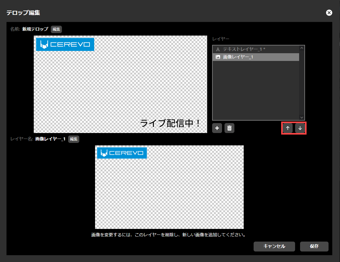
Changing the layer stacking order
レイヤー一覧において、重ね順を変更するレイヤーを選択し、「↑」または「↓」を押すことで、レイヤーの重ね順を変更することができます。より上位にあるレイヤーが前面に合成されます。
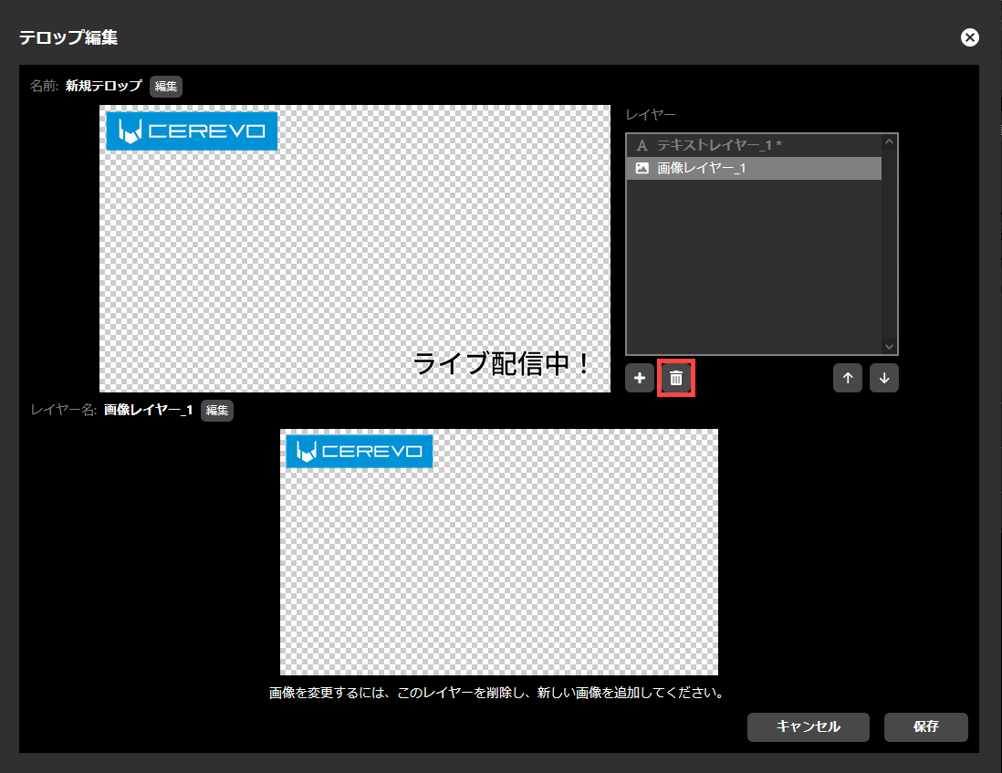
Deleting layers
レイヤー一覧において、削除したいレイヤーを選択し、ごみ箱アイコンを押すと、選択したレイヤーを削除することができます。削除したレイヤーは復元できません。
Saving captions
レイヤーの追加および編集後、「保存」ボタンを押すと、テロップを保存し、編集を終了します。なお、「キャンセル」を押すと、編集内容を保存せずに終了します。
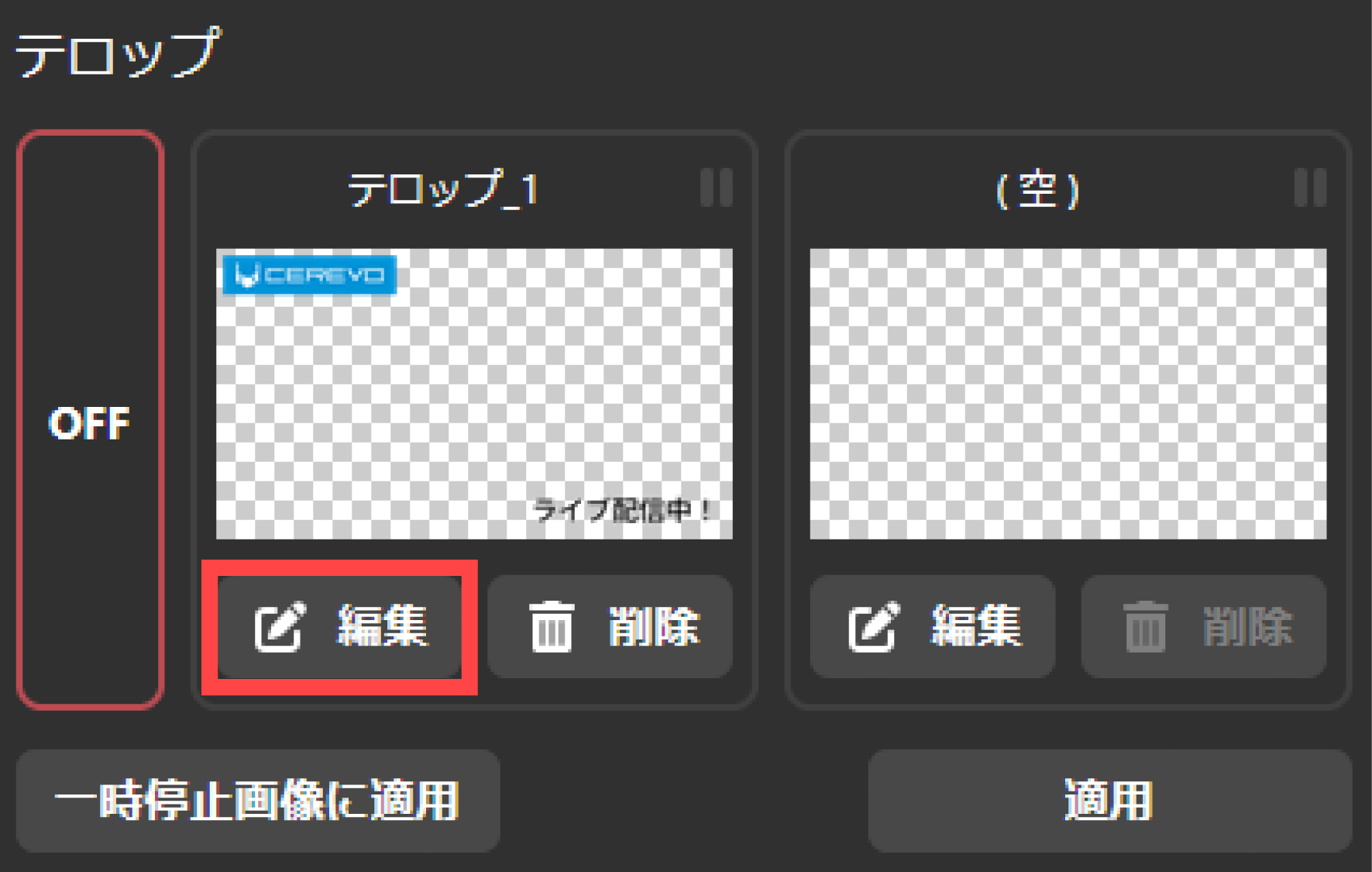
Re-editing a caption
テロップのサムネイルの横にある「編集」アイコンを押すことで再編集を行うことができます。再編集では、レイヤー順序の変更や、レイヤーの差し替え、テキストレイヤーの再編集などを行うことができます。
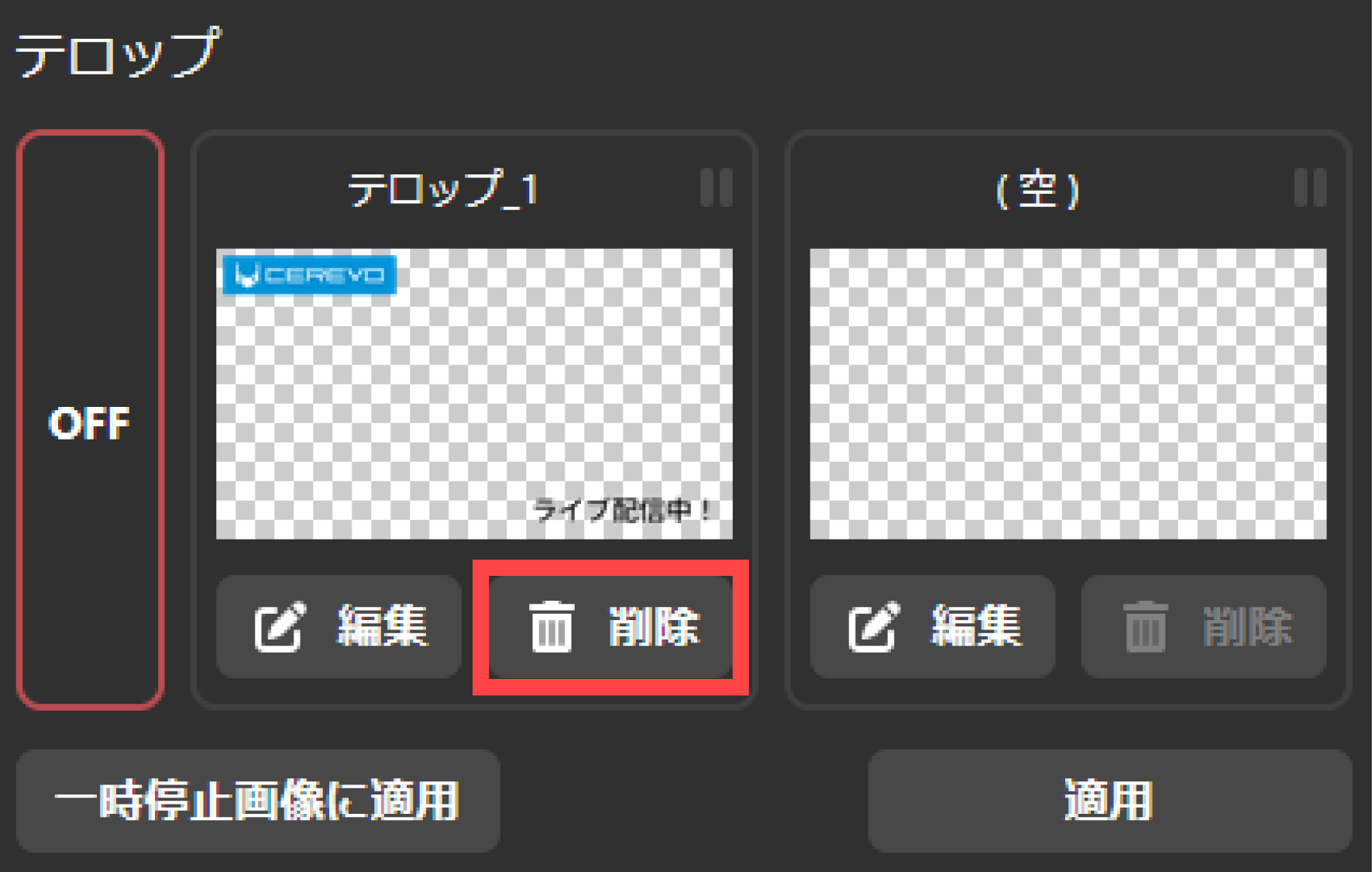
Deleting a caption
テロップのサムネイルの横にある「削除」アイコンを押すことで削除することができます。いったん削除したテロップは、復元できません。
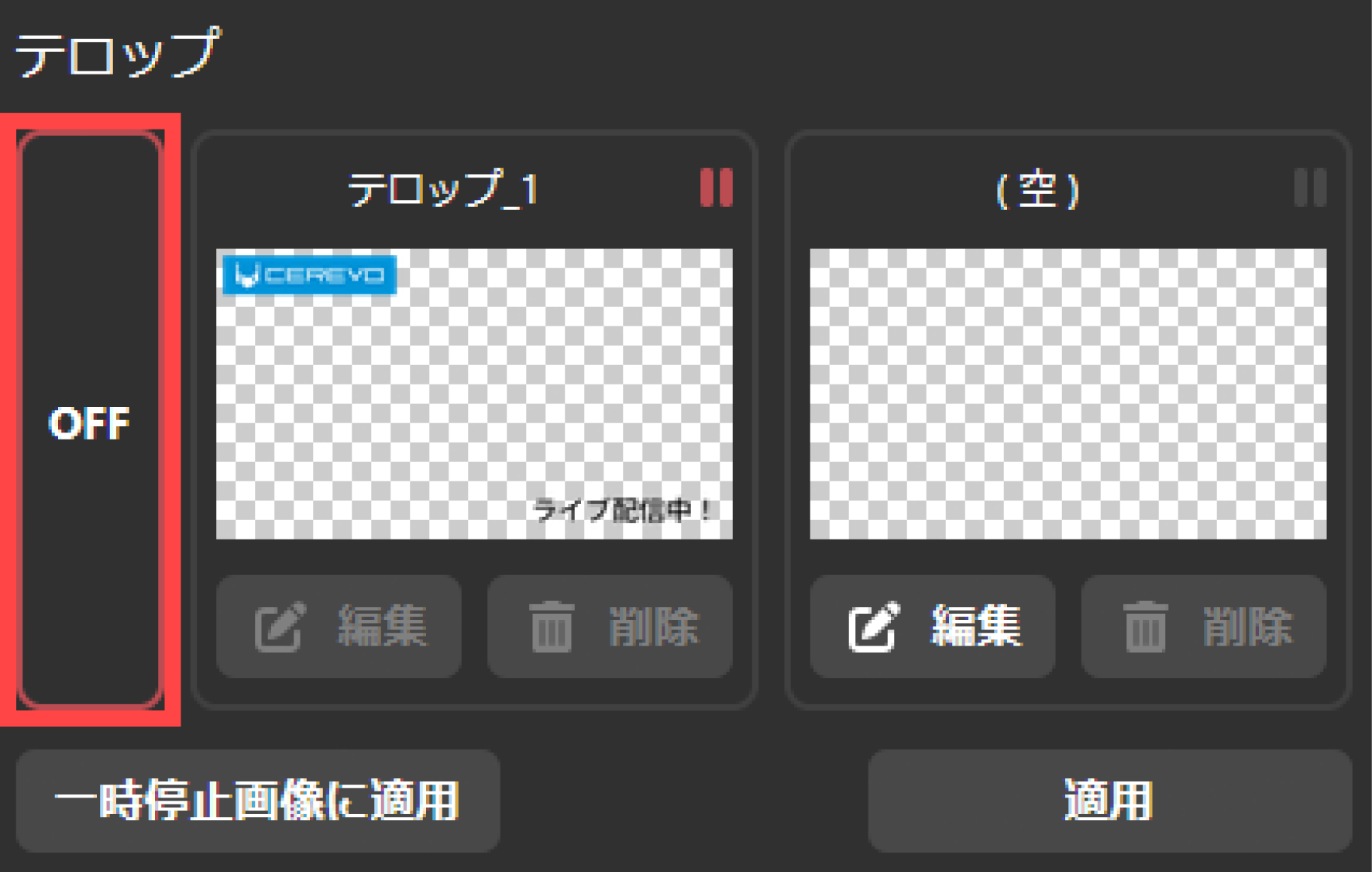
9-2 How to combine captions
To combine a caption you created with the streaming video, please do the following.
適用したいテロップのサムネイルを押して選択状態とします。
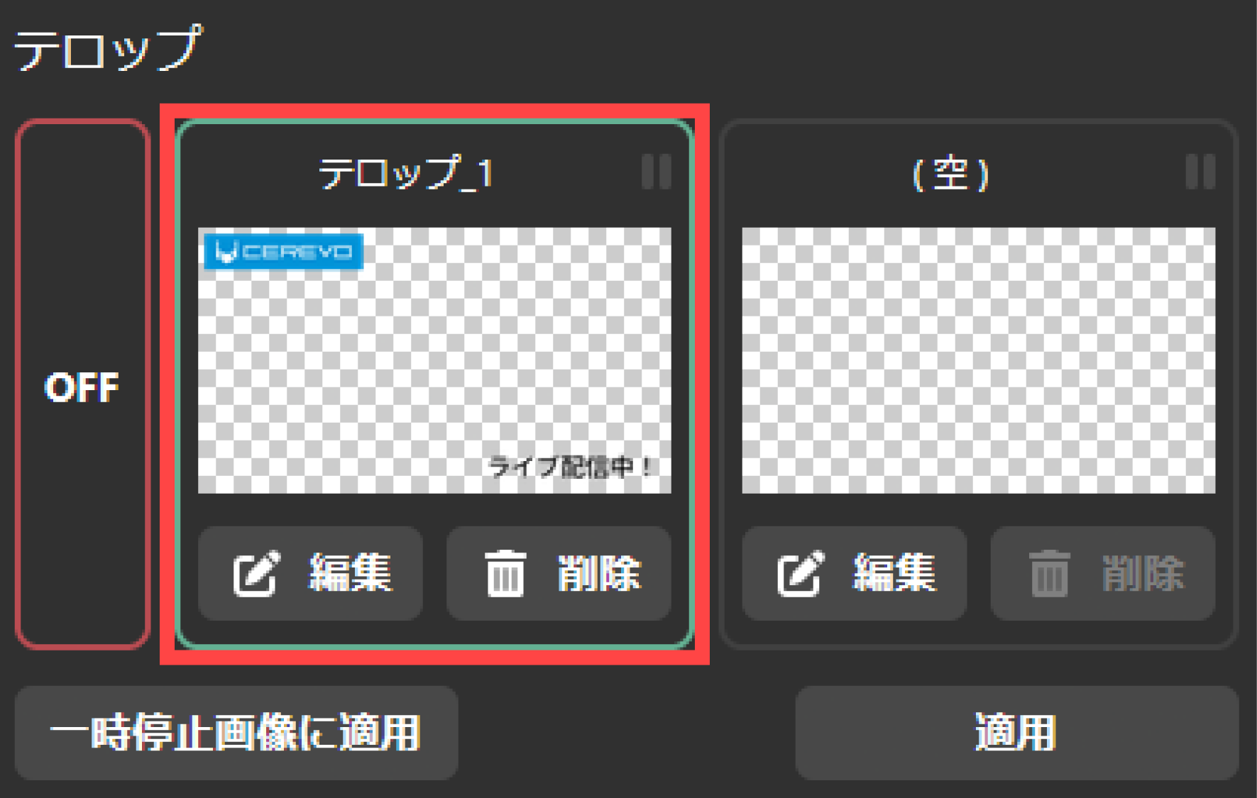
右下の「適用」ボタンをクリックします。
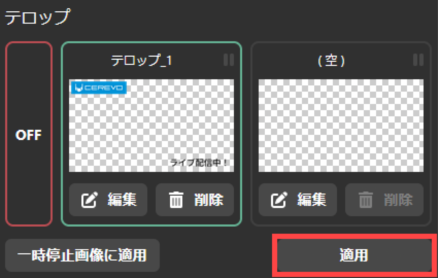
If you select a new caption and apply it while already combining another caption, the caption to be combined will be changed to the newly selected caption.
To stop combining captions with the streaming video, do the following.
テロップサムネイル左側に表示されている「OFF」を押してください。
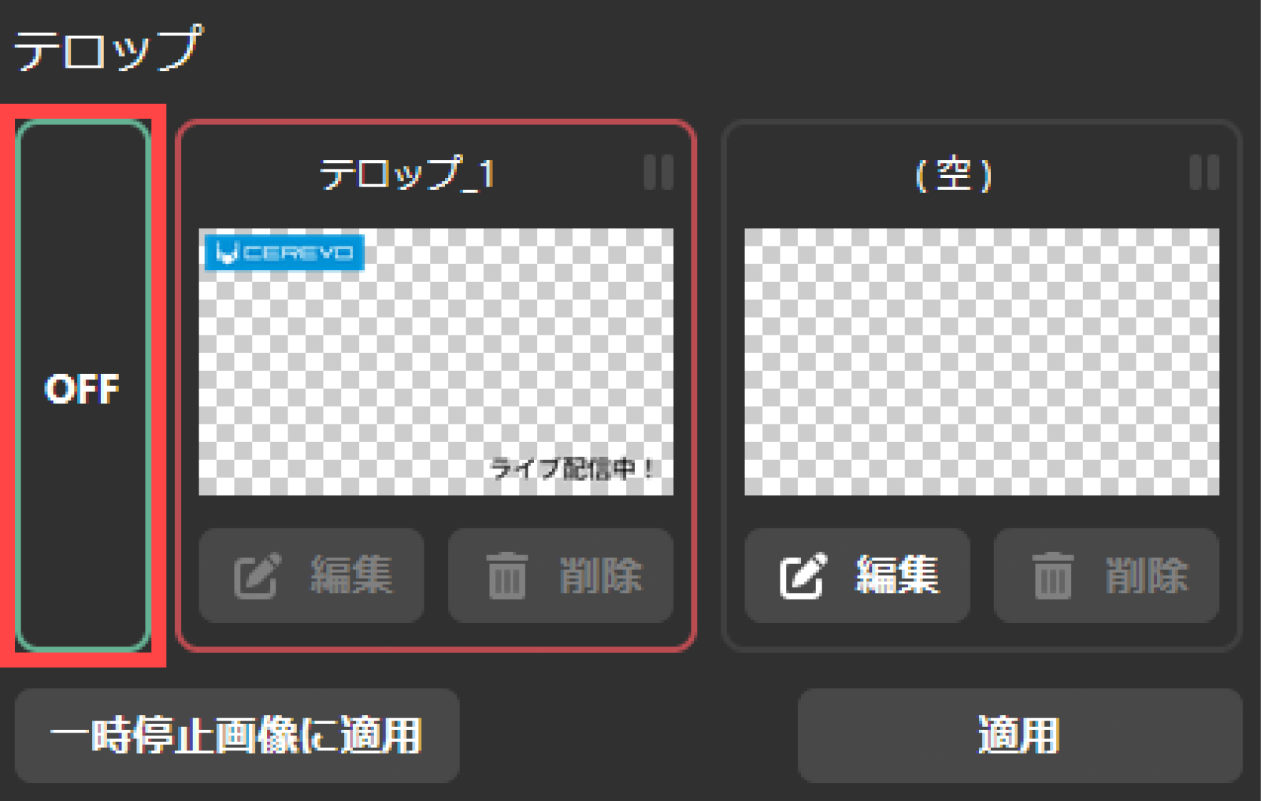
右下の「適用」ボタンをクリックします。
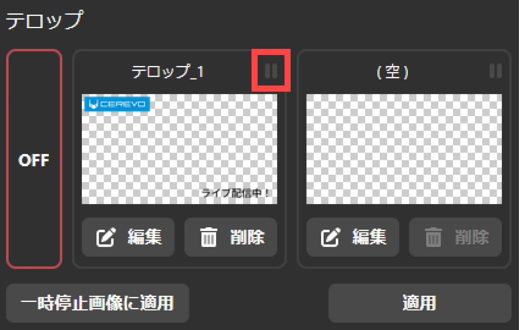
9-3 How to combine pause captions
You can display the captions you created above even when you pause streaming or recording.\ Please note that only one set of pause captions can be combined.
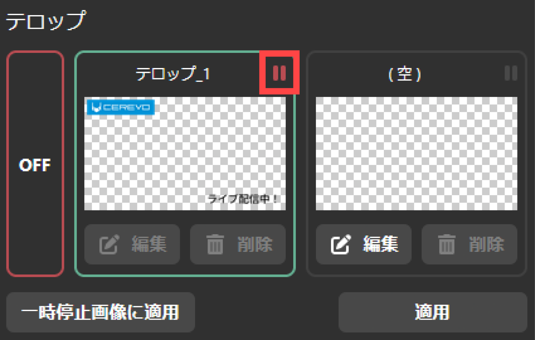
To combine the captions you created with the paused streaming video, please do the following.
適用したいテロップのサムネイルを押して選択状態とします。

左下の「一時停止画像に適用」ボタンをクリックします。

テロップ名称の右横に「赤い一時停止」アイコンが表示されます。
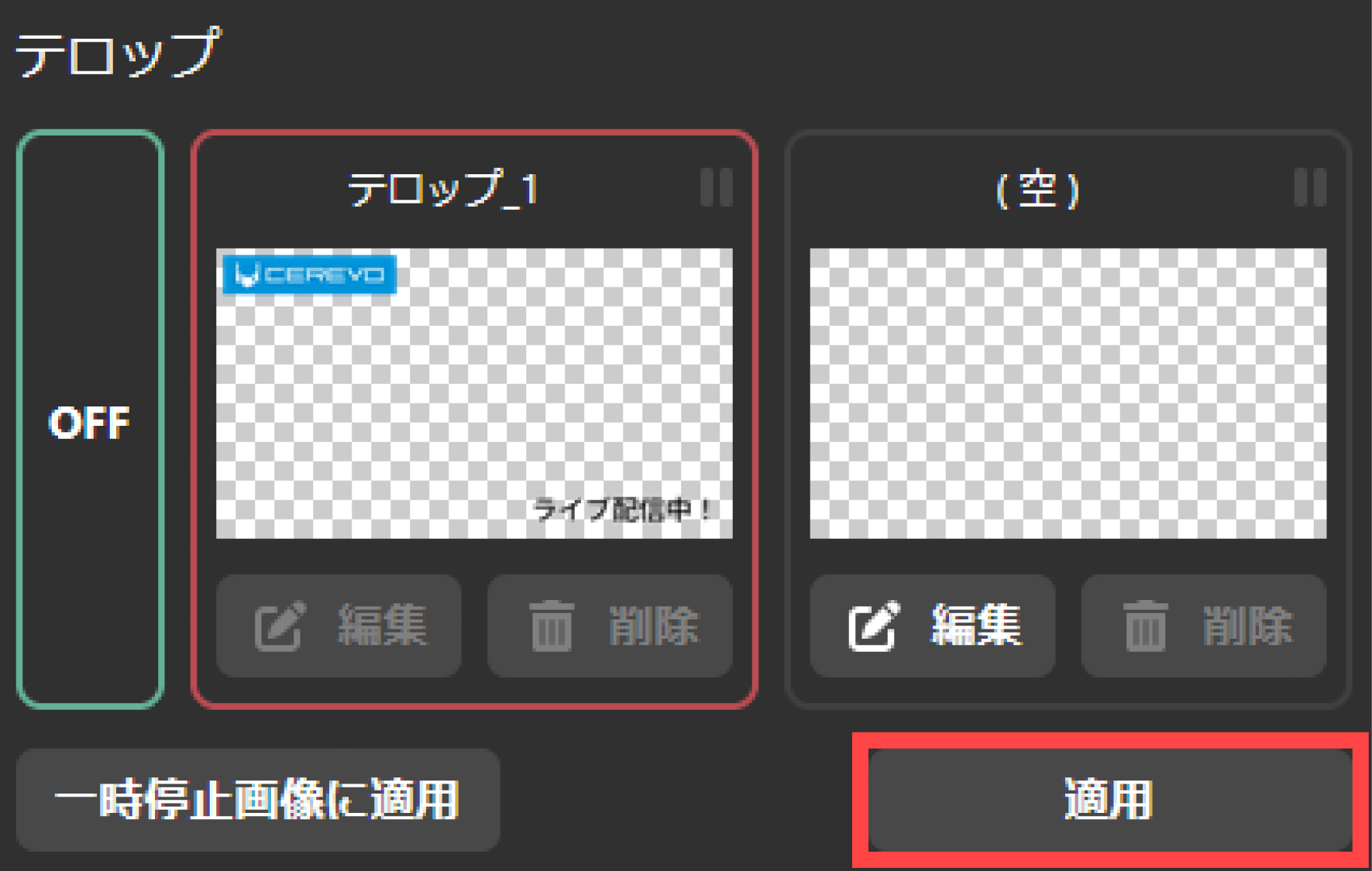
To stop combining pause captions, please do the following.
テロップサムネイル左側に表示されている「OFF」を押してください。
左下の「一時停止画像に適用」ボタンをクリックします。
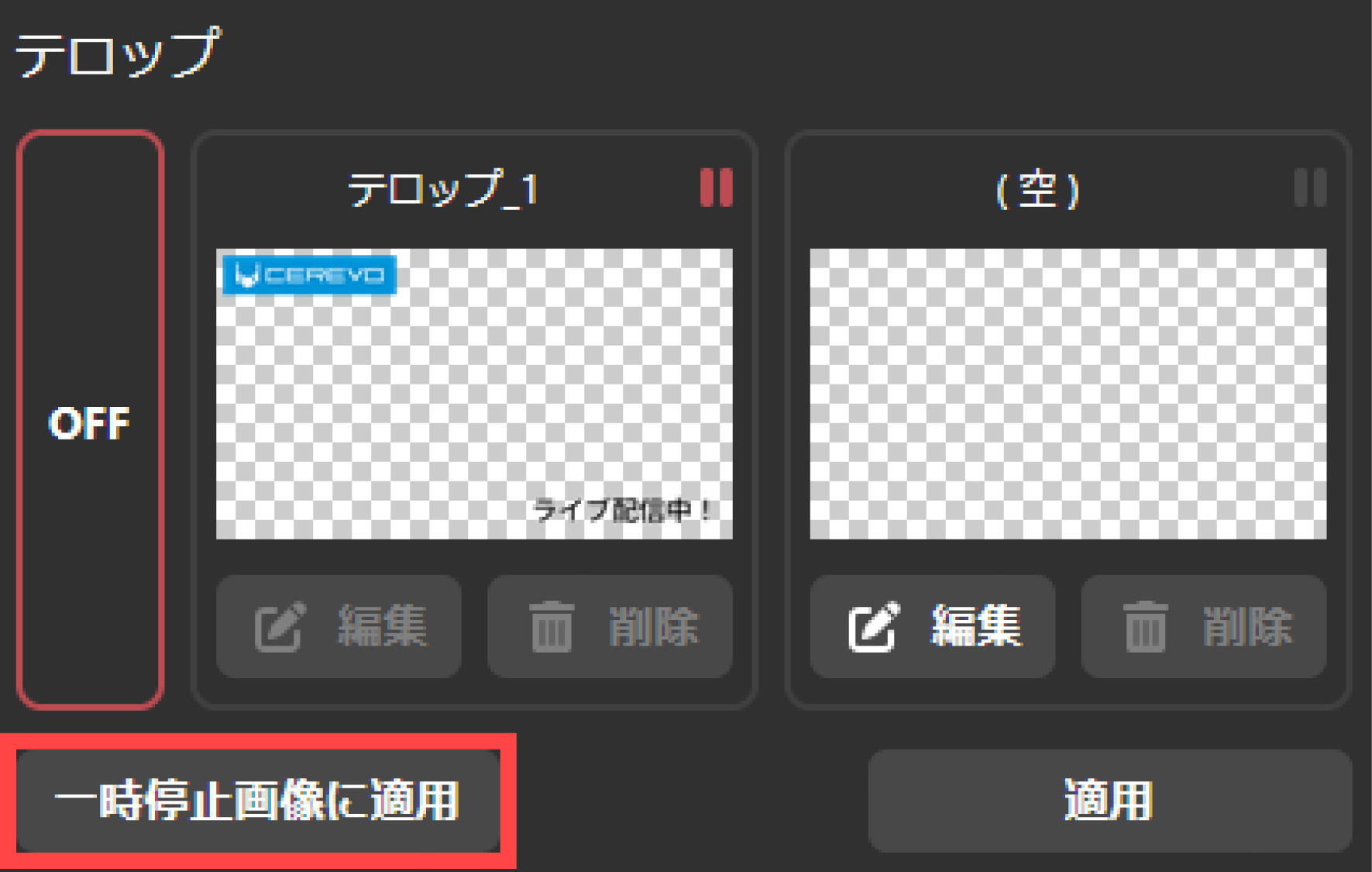
テロップ名称の右横に「赤い一時停止」アイコンの表示が消えます。
10 More convenient ways to use this product
This chapter explains how to use this product more conveniently.
Auto-boot settings
This product can be set to start automatically when power is supplied from the AC adapter.
To set this, follow the steps below. Auto-start settings can be made from the main UI. It cannot be set from LiveShell Studio.
Push the operation button on the top right once on the offline top screen.
Use the operation buttons on the bottom right and bottom left to move the cursor to “Automatic Boot”.
Push the operation button on the top right to confirm your selection.
Use the operation buttons on the bottom right and bottom left to move the cursor to “ON” and select it. The setting will be applied when you select it.
Auto Start Setting
This product can be set to automatically start streaming when the network status is online.
To set it up, follow the steps below. This can be done from LiveShell Studio or the main UI.
Setting using LiveShell Studio
Select “Auto Start” from the pull-down menu in “Auto Control” displayed on the desired channel for which you want to set up.
Click the “Apply” button to apply the settings.
Setting using the unit buttons
Push the operation button on the top right of the main screen once while online.
Use the operation buttons on the bottom right and bottom left to move the cursor to the desired “Video Stream” channel you want to set.
Push the operation button on the top right to confirm your selection.
Use the bottom right and bottom left operation buttons to move the cursor to “Automatic Control #n”.
Push the operation button on the top right to confirm your selection.
Use the operation buttons on the bottom right and bottom left to move the cursor to “Auto Start” and select it. The settings will be applied when you select it.
Automatic control settings
This product can be set so that when any channel starts or stops broadcasting, other channels will follow the same.
For example, if you set “Follow channel #0” for channel #1, when channel #0 starts broadcasting, channel #1 will also automatically start broadcasting.
To set it up, follow the steps below. This can be done from LiveShell Studio or the main UI.
Setting using LiveShell Studio
Select “Follow channel #n” from the pull-down menu in “Automatic control” displayed on the desired channel. Select any channel number.
Click the “Apply” button to apply the settings.
Setting using the unit buttons
Push the operation button on the top right of the main screen once while online.
Use the operation buttons on the bottom right and bottom left to move the cursor to the desired “Video Stream” channel you want to set.
Push the operation button on the top right to confirm your selection.
Use the bottom right and bottom left operation buttons to move the cursor to “Automatic Control #n”.
Push the operation button on the top right to confirm your selection.
Use the operation buttons on the bottom right and bottom left to move the cursor to “Follow channel #n” and select it. Select any channel number. The settings will be applied when selected.
Audio stream settings
This product can input separate audio signals to the left and right audio sources and send them out as independent audio streams.
For example, input Japanese audio to the L channel of the audio source and set the audio stream #0 channel to mono (left), input English audio to the R channel of the audio source and set the audio stream #1 channel to mono (right). Set audio stream #0 to distribute Japanese audio on channel #0, and audio stream #1 to distribute English audio on channel #1. With this settings, it is possible to distribute the same video on channel #0 and channel #1, but different audio on each channel.
Tip
For normal streaming, there is no need to set the audio stream, and the audio stream settings for each channel can be left at the default value of #0.
If you change the audio stream, take this product offline after making the change and then online again. Changes will not be reflected if this product is online.
To set it up, follow the steps below. This can be done from LiveShell Studio or the main UI.
To set up, follow the steps below. This can be done from LiveShell Studio or the main UI.
Setting using LiveShell Studio
Enter a value in the “Bitrate” input field displayed in the desired channel (#0 or #1) you wish to operate.
Click the “Apply” button to apply the settings.
Setting using the unit buttons
Push the operation button on the top right of the main screen once while online.
Use the operation buttons on the bottom right and bottom left to move the cursor to the desired “Audio Stream” channel you wish to set.
Push the operation button on the top right to confirm your selection.
Use the operation buttons on the bottom right and bottom left to move the cursor to “Audio kbps”.
Push the operation button on the top right to confirm your selection.
Use the operation buttons on the bottom right and bottom left to enter a value in the input field.
Reboot this product or switch it offline and then online again. The settings will not be updated if the product is online.
Audio stream channel settings
The operation of each channel is as follows:
Monaural
Mono stereo audio where the audio input to the L channel and R channel are mixed
Mono (Left)
Mono stereo audio with only the audio input to the L channel
Mono (Right)
Mono stereo audio with only the audio input to the R channel
Stereo
Stereo audio where the audio input to the L channel and R channel is not mixed
Setting using LiveShell Studio
Select the desired setting from the pull-down menu in “Channel” displayed in the desired channel (#0 or #1) you want to operate.
Reboot this product or switch it offline and then online again. The settings will not be updated if the product is online.
Setting using the unit buttons
Push the operation button on the top right of the main screen once while online.
Use the operation buttons on the bottom right and bottom left to move the cursor to the desired “Audio Stream” channel you wish to set.
Push the operation button on the top right to confirm your selection.
Use the operation buttons on the bottom right and bottom left to move the cursor to “Channel”.
Push the operation button on the top right to confirm your selection.
Use the operation buttons on the bottom right and bottom left to move the cursor to the desired setting and select it.
Reboot this product or switch it offline and then online again. The settings will not be updated if the product is online.
AV Sync Adjustment Settings
This product allows you to set the delay correction for the analog audio source input to the 3.5mm stereo LINE IN terminal.
When inputting video from the HDMI IN terminal and audio to the 3.5mm stereo LINE IN terminal, there may be a delay between the video and audio. In such cases, you can use this setting to adjust the synchronization between the video and audio.
To set it up, follow the steps below. This can be done from LiveShell Studio or the main UI.
Setting using LiveShell Studio
Click the “Audio” button displayed on the desired channel for which you want to set up.
Enter the desired value in the “Adjust audio delay” input field that appears.
Click the “Apply” button to apply the settings.
Setting using the unit buttons
Push the operation button on the top right of the main screen once while online.
Use the operation buttons on the bottom right and bottom left to move the cursor to the desired “Video Stream” channel you want to set.
Push the operation button on the top right to confirm your selection.
Use the operation buttons on the bottom right and bottom left to move the cursor to “AV Sync Adjustment”.
Push the operation button on the top right to confirm your selection.
Use the operation buttons on the bottom right and bottom left to enter a value in the input field.
When setting with the main unit UI, the setting will be applied as soon as you enter the desired value in the input field.
Aspect and Crop Settings
This product allows you to manually change the screen size for streaming. By using this function, you can stream not only horizontally oriented video but also vertically oriented video such as that shot with a smartphone.
To set up, follow the steps below. This can be done in LiveShell Studio. It cannot be set in the main UI.\ Note that this setting can only be set for channel #1 and channel #2, and cannot be set for channel #0.
Click the “Aspect and crop” button displayed for the desired channel for which you want to set up.
Select the desired setting from the “Crop mode” pull-down menu.
To set the overscan ratio, enter the desired value in the “Overscan ratio” input field.
The overscan rate can only be set when a crop type other than “Manual” is selected. When “Manual” is selected for the crop type, the “Manual Aspect Ratio” can be set instead of the overscan rate. To set the manual aspect ratio, enter the desired values in the “X”, “Y”, “Width”, and “Height” input fields.The width and height indicate the width and height of the cropping range, and X and Y indicate the coordinates of the upper left point of the cropping range, with the upper left corner of the input image as the origin. After cropping, the image will be enlarged or reduced to the height set in “Vertical Resolution” while maintaining the aspect ratio.
Click the “Apply” button to apply the settings.
Screensaver settings
This product is equipped with a screensaver.
The main display of this product uses OLED. Due to the characteristics of OLED, if the same screen is displayed for a long time, the screen may burn in. To avoid this, use the screensaver. When the screensaver is turned on, if the main UI is not used for a specified period of time, it will move a specific display up and down to prevent screen burn in.
To set it up, follow the steps below. This operation can not be done in LiveShell Studio. It can be done in the main UI.\ Note that this setting does not work when the top screen of a channel that is streaming or recording is displayed.
Setting while the unit is offline
Push the operation button on the top right once on the offline top screen.
Use the operation buttons on the bottom right and bottom left to move the cursor to “Broadcasting”.
Push the operation button on the top right to confirm your selection.
Use the operation buttons on the bottom right and bottom left to move the cursor to “Screen Saver”.
Push the operation button on the top right to confirm your selection.
Use the operation buttons on the bottom right and bottom left to select the desired value. The settings will be applied once you have made your selection.
Setting while the unit is online
Push the operation button on the top right of the main screen once while online.
Use the operation buttons on the bottom right and bottom left to move the cursor to “Screen Saver”.
Push the operation button on the top right to confirm your selection.
Use the operation buttons on the bottom right and bottom left to select the desired value. The settings will be applied once you have made your selection.
Brightness setting for the 3 streaming button indicators
The brightness of the 3 streaming button indicators on this product can be adjusted.
To set it up, follow the steps below. This operation can not be done in LiveShell Studio. It can be done in the main UI.
Setting while the unit is offline
Push the operation button on the top right once on the offline top screen.
Use the operation buttons on the bottom right and bottom left to move the cursor to “Broadcasting”.
Push the operation button on the top right to confirm your selection.
Use the operation buttons on the bottom right and bottom left to move the cursor to “LED Brightness”.
Push the operation button on the top right to confirm your selection.
Use the operation buttons on the bottom right and bottom left to set the desired value. The value will be applied when set.
Setting while the unit is online
Push the operation button on the top right of the main screen once while online.
Use the operation buttons on the bottom right and bottom left to move the cursor to “LED Brightness”.
Push the operation button on the top right to confirm your selection.
Use the operation buttons on the bottom right and bottom left to set the desired value. The value will be applied when set.
Setting the main unit operation lock
This product is equipped with a lock function that disables the button operation of the main unit.
To set it up, follow the steps below. This can be done from LiveShell Studio or the main UI.
Setting using LiveShell Studio
Click the “Lock” button displayed in “Main unit operation lock”.
Setting using the unit buttons
Press the operation button at the top left of the online top screen once.
Push the operation button on the top right. This will lock the unit’s operations.
To unlock it, push and hold the operation buttons on the bottom left and bottom right at the same time.
How to remove the built-in battery
The built-in battery installed in this product can be removed. To remove it, follow the steps below.
If an AC adapter is connected to this product, remove the AC adapter.
Remove the two screws on the bottom of the unit.
Remove the battery cover.
Remove the battery, by pressing the latch on the connector connected to the end of the cable to unlock it, and then remove the cable. DO NOT PULL the connector or cable with excessive force, as this may damage the connector.
11 Firmware Update Guide
This chapter explains how to update the firmware for this product.
To perform a firmware update, you must complete 4-2 Network Connection for this product.
11-1 How to update the firmware
To automatically update to the latest firmware, please follow the steps below.
Connect the AC adapter to the power input terminal on the back of the unit.
Push the operation button on the top right once on the offline top screen.
Use the operation buttons on the bottom right and bottom left to move the cursor to “Upgrade FW”.
Push the operation button on the top right to confirm your selection.
Use the operation buttons on the bottom right and bottom left to move the cursor to “Yes”.
Push the operation button on the top right to confirm your selection.
If a newer version of firmware is released than the currently installed firmware, it will automatically update to the latest firmware. NEVER REMOVE THE AC ADAPTER during the update.
The unit will automatically reboot when the firmware update is complete.
11-2 How to update firmware manually
To manually update to a desired firmware, please follow the steps below.
To update the firmware, you need a USB memory stick that is 32GB or less and formatted in FAT32 with sufficient free space. Firmware updates cannot be performed using microSD cards or USB memory sticks with a capacity of more than 32GB.
Download the firmware from the release notes page of the firmware version you want to update to.\ → LiveShell X Firmware Release Notes
Make sure the downloaded updater file is named updater.bin. If it is not, change it to updater.bin.
Copy updater.bin to the root of the USB memory (top folder).
Insert the USB memory into the Wi-Fi USB adapter port on the back of the unit.
Connect the AC adapter to the power input terminal on the back of the unit.
Push the operation button on the top right once on the offline top screen.
Use the operation buttons on the bottom right and bottom left to move the cursor to “Update via USB”.
Push the operation button on the top right to confirm your selection.
Use the operation buttons on the bottom right and bottom left to move the cursor to “Yes”.
Push the operation button on the top right to confirm your selection.
The firmware update will begin. DO NOT REMOVE THE AC ADAPTER during the update.
The unit will automatically reboot when the firmware update is complete.
12 Initialization and forced shutdown operations
This chapter describes how to install this product and connect external devices.
12-1 Initialization
This operation deletes all the settings information of this product and returns it to the factory settings.\ *This operation cannot be undone. Please consider carefully before proceeding.
To initialize, follow the procedure below. This operation can be performed from the main UI. It cannot be done from LiveShell Studio.
Push the operation button on the top right once on the offline top screen.
Use the operation buttons on the bottom right and bottom left to move the cursor to “Initialize”.
Push the operation button on the top right to confirm your selection.
Use the operation buttons on the bottom right and bottom left to move the cursor to “Yes”.
Push the operation button on the top right to confirm your selection.
The initialization operation will start. Once initialization is complete, the product will automatically restart.
12-2 Forced shutdown
This is a forced shutdown operation to be performed when a phenomenon occurs in which this product becomes inoperable.\ *If a forced shutdown is performed, data stored inside this product, such as setting data and subtitle images, may be damaged or lost.
To force shutdown, follow the procedure below. This can be done from the device’s UI. It cannot be done from LiveShell Studio.
Push and hold the top left and bottom right operation buttons at the same time for about 5 seconds.
The OLED display will go blank and the device will shut down.
After confirming that the OLED display has gone blank, restart the device.